Abstract
Linear ultrasonic motor (LUSM) is a new type of driver. LUSM has many advantages, so it is taken seriously in aeronautics and astronautics. But, because of the deficiency of studies on the performance of LUSM in abnormal temperature, it’s necessary to do research on the performance of LUSM in different ambient temperature, to confirm whether it can work under abnormal temperature and how it works. In this research, we use V type LUSM (VLUSM) as the test object, owing to that VLUSM is one basic type of linear ultrasonic motor. When doing research, we pay close attention to the moment of force and the rotation rate of VLUSM, to discover how much they change in abnormal temperature environment. This research compares all datum partitioned by different temperature, and uses figures to show the tendency of those mechanical properties in abnormal temperature. At the same time, we explain the changing by means of theories. Finally, through detailed experimental demonstration, we believe that as the temperature rises, both moment of force and rotation rate of VLUSM increase, and we can also conclude that VLUSM can work normally under abnormal temperature environment.
1. Introduction
As a new type of driver, linear ultrasonic motor (LUSM) has many advantages, such as the high torque with low velocity, the quick response, the simple structure, the magnetic-field noninterference, the auto lock with interruption of power supply and so on [1]. It takes advantage of the inverse piezoelectric effect of the piezoelectric ceramics. Due to the friction between the active cell and the stator, the micro vibration of the stator is transformed into the macro linear motion of the active cell, with the electrical energy transforming into the mechanical energy at the same time. Recently, many utilizations and tests [2-4] about ultrasonic motor (USM) are carried out, some of which are about the reliability in abnormal environment. For example, before being used in the Mars probe, ultrasonic motor is widely tested in the abnormal environment experiments. In which, high-low temperature is a basic factor in the specific working environment. Also, to ensure its reliability in the specific working environment, it is necessary to do research on LUSM in abnormal environment. This research treats the temperature and the pretightening force level as the external variables, to explore the phenomena and the rules of VLUSM in abnormal temperature environment. And this research compares all datum partitioned by different temperature, to show the tendency of those mechanical properties in abnormal temperature. The results show that as the temperature goes up, both the moment of force and the rotation rate of VLUSM will increase, and VLUSM can work normally under abnormal temperature environment.
2. Test equipments and method
2.1. Test object
This research uses V type LUSM as the testing object. The material of elastic body is 65 Mn. Fig. 1 shows the entity of V type LUSM. Because of its two Langevin vibrators fixed like the grapheme “V”, we call this type LUSM “V type LUSM”. This type is designed based upon one type designed by Kurosawa from Japan [5], which utilizes effect of the piezoelectric ceramics. Two Langevin vibrators are motivated by two sine signals with the same frequency but the phase difference of 90 degrees simultaneously, yearning elliptical motion at the driving foot.
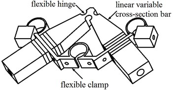
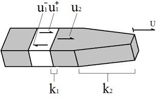
Compared with normal VLUSM, three main adjustments are made on this type of VLUSM we use in the experiments, as Fig. 2 shows: linear variable cross-section bar, flexible hinge and flexible clamp [6, 7]. First, based on the principle of ultrasonic amplitude transformer, the VLUSM adopts two bars of linear variable cross-section, replaceing two bars of equal cross-section, because the bar of linear variable cross-section can improve the efficiency of the VLUSM. Second, two bars are connected by the flexible hinge at the driving foot. Because of minor rigidity of the flexible hinge, the vibration amplitude at the driving foot is increased effectively when the VLUSM works. Third, two bars are linked by the flexible clamp, having eliminated the interval in the normal clamp, improving the running performance and stability of the VLUSM, and removing the disturbing modals. Many tests have indicated that the improved VLUSM has favorable output characteristics.
Fig. 1The entity of V type LUSM
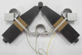
Fig. 2Three main adjustments of V type LUSM
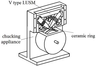
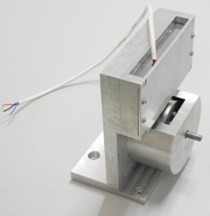
To be convenient to collect datum, a chucking appliance is designed as Fig. 3 shows. It transforms the micro to-and-fro linear vibration of stator into the macro linear motion of the active cell (the ceramic ring), the friction layer of which is made up of .
Fig. 3The model a) and entity b) of the chucking appliance
(a)
(b)
2.2. Test equipment
The composite environment trial box, controlled by the control system, as Fig. 4 shows, is main equipment in the test. This box can simulate high-low temperature and vacuum environment. The working temperature scope is –100°C~+100°C. Before the test, the VLUSM, which is fixed by the chucking appliance, is placed into the test box. The photoelectric encoder and the torque sensor, which are used to measure the moment of force and rotation rate of the VLUSM, are put out of the test box, to ensure their normal working condition. The power amplifier and the signal generator are outside of the test box, controlling the VLUSM. The magnetic-lag machine is used to apply loads to the VLUSM. The input and output signals are transmitted by the wires connecting inner and outer box.
Fig. 4Test equipments
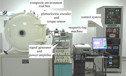
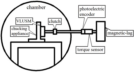
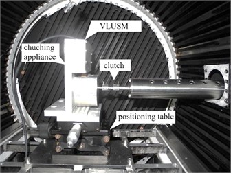
Fig. 5 shows both the principle and the picture of the arrangement at the chamber of the composite environment trial box. The VLUSM, which is fixed by the chucking appliance, is placed on the positioning table. The clutch, designed as it looks like, is used to ensure the flexibility of the mechanism when the coaxiality is low.
Fig. 5The principle a) and the picture b) of the arrangement at the chamber
(a)
(b)
2.3. Test project
To obtain the influence on the VLUSM by temperature, the temperature condition is divided into 7 levels. They are –40°C, –20°C, 0°C, 20°C, 40°C, 60°C and 80°C. To observe the effect of the pretightening force on the performance of the VLUSM in different temperature environment, three pretightening force levels are set. They are 30 N, 40 N and 50 N. This research sets independent variables (temperature and pretightening force) and two dependent variables (moment of force and rotation rate), to show the changing of the performance.
The loads on the VLUSM are provided by the magnetic-lag machine. Before the test, the resonance frequency is measured by the frequency-analysis device. It is between 32 kHz and 33 kHz. So the regulation scope of signal generator can be comfirmed. The voltage set by the power amplifier is , to motivate the performance of piezoelectric ceramics. To ensure the influence on the VLUSM by different temperature, the dependent variables can be measured after waiting for 20 minutes at one temperature level.
The objective of the test is to gain the optimum rotation rates at the resonance frequency, per temperature and per pretightening force level, and to gain the load characteristics, per temperature and per pretightening force level. The unload rotation rate is the rotation rate without loads, and stalling torque is the torque with 0 rotation rate.
3. Test results
In different temperature and pretightening force levels, the mechanical properties of the VLUSM can be measured by two factors: velocity and torque. When pretightening force is 30 N, the running velocity is the maximum of three pretightening force levels, so the sensibility of the running velocity to the temperature is the most. For the convienence of observation, we illustrate mechanical properties in 30 N pretightening force alone. Fig. 6 shows the load-characteristic of the VLUSM, in different temperature and in 30 N pretightening force. The load-characteristics in other pretightening force levels possess same change tendency.
From Fig. 6, both the running velocity and the moment of force increase in pace with the increasing of the temperature. But the amplitudes decrease in pace with the increasing in the temperature. Also, when the temperature is at or over 40°C the running velocity scarcely changes.
Fig. 7 shows the unloaded velocity of the VLUSM in different temperature in 30 N pretightening force. Obviously, the unloaded velocity increases in pace with the increasing of the temperature. But the increasing amplitude of the unloaded velocity decreases when the temperature rises.
Fig. 6Load-characteristic of VLUSM in 30 N
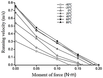
Fig. 7The unloaded velocity of the VLUSM in 30 N
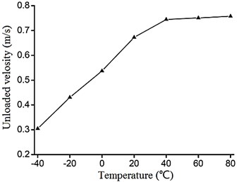
Fig. 8 shows the stalling torque of the VLUSM in different temperature in 30 N pretightening force. Also, the stalling torque increases in pace with the increasing of the temperature. But the increasing amplitude of the stalling torque decreases when the temperature rises, although the phenomenon is not very clear.
Fig. 9 shows the unloaded velocity of the VLUSM in different temperature and different pretightening force levels. As Fig. 9 shows, the unloaded velocity is faster when the pretightening force is lower. Besides, when the pretightening force level becomes higher, the decreasing amplitude of the unloaded velocity decreases, at a given temperature.
Fig. 8The stalling torque of the VLUSM in 30 N
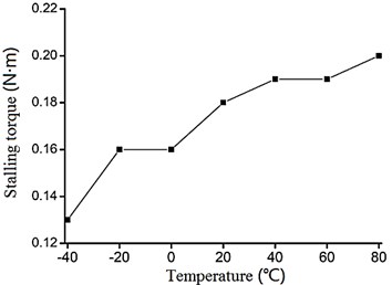
Fig. 9The unloaded velocity of the VLUSM in different pretightening force levels
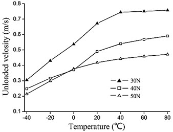
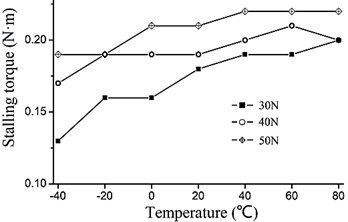
Fig. 10 shows the stalling torque of the VLUSM in different temperature and different pretightening force levels. From Fig. 10, we can find that the stalling torque becomes higher when the pretightening force level becomes higher, at a given temperature.
Fig. 10The stalling torque of the VLUSM in different pretightening force levels
4. Test analysis
4.1. The influence of different pretightening force levels
First of all, we explain the mechanical properties of the VLUSM in different pretightening force levels.
When the pretightening force level changes, both moment of force and rotation rate of the VLUSM will change. Specifically, when the pretightening force level becomes higher, the rotation rate of the VLUSM will decrease, but the moment of force will increase. Besides, the decreasing amplitude of the rotation rate decreases along with the increasing of the pretightening force level.
Because along with the increasing of the pretightening force level, the friction resistance to the VLUSM increases, so the rotation rate decreases, as Fig. 9 shows. At the same time, due to the increasing of the pretightening force level, the area of the friction interface increases. Therefore, the mechanical transmission efficiency increases, between the active cell and the stator of the VLUSM. So the moment of force increases, as Fig. 10 shows.
4.2. The influence of different temperature
Secondly, we explain the mechanical properties of the VLUSM in different temperature.
When the temperature changes, both moment of force and rotation rate of the VLUSM will change. Specifically, when the temperature becomes higher, the rotation rate of the VLUSM will increase, and the moment of force will increase. Besides, the increasing amplitude of the rotation rate decreases along with the increasing of temperature.
The piezoelectric ceramic chaps play a very important role in the energy conversion when the VLUSM runs. So the function of the piezoelectric ceramic chaps affects the mechanical properties of the VLUSM directly. In general, the temperature affects the the function of the piezoelectric ceramics considerably. So the influence on the VLUSM by the temperature is considerable.
The electromechanical coupling effect of the piezoelectric ceramics is caused by the coupling of mechanical varieties, such as the stress and the strain , and electrical varieties, such as the electric field intensity and the electric displacement . Electric field intensities , and , which are applied respectively along directions of polarization , and , can motivate strains in the internal ceramic chaps, as Fig. 11 shows. This effect is called inverse piezoelectric effect. For the polaxis of piezoelectric ceramic chaps is , only three piezoelectric constants , and are useful, refer to Eq. (1):
where is the strain matrix, is the piezoelectric constant matrix, and is the the electric field intensity matrix.
So, the strain in the direction of can be gained, refer to Eq. (2):
Suppose that for single Langevin vibrator of the VLUSM, the amplitude of vibration at its driving foot can be described as Eq. (3):
where is the amplitude of the vibration at driving foot of single Langevin vibrator, is the thickness of the piezoelectric ceramic chaps of single Langevin vibrator. is the amplification coefficient of the vibrating amplitude of the whole vibrator, and , in which is the amplification coefficient caused by different materials, and is the amplification coefficient caused by the linear variable cross-section bar [8].
Now, we specifically illustrate these two amplification coefficients of the vibrating amplitude and . Fig. 12 shows the influence on the displacements of the vibration in different phases by two amplification coefficients, where the incoming wave is motivated by the piezoelectric ceramic chaps, the transmission wave is transmitted in the elastic body, and the reflected wave is transmitted in the piezoelectric ceramic chaps. Eq. (4) describes the relation between the incoming wave and the amplitude of vibration of the piezoelectric ceramic chaps:
Fig. 11The diagrammatic sketch of single Langevin vibrator of the VLUSM
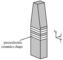
Fig. 12Two amplification coefficients of the vibrating amplitude of single vibrator
First, consider the influence on by the temperature. Suppose that an ideal Langevin vibrator is of equivalent cross-section and composed of the elastic body and the piezoelectric ceramic chaps (where we do not consider the influence of the screw bolt, the hole on the chaps and the copper sheets), the relation of the displacements between different materials can be described as Eq. (5), based on the continuity of displacements and velocities:
where and are the acoustic velocity and the density of the piezoelectric ceramics, and and are the acoustic velocity and the density of the elastic body.
When the temperature rises, the changing of the density is negligible, so the density of both the piezoelectric ceramics and the elastic body can be regarded as the constants. And in the ordinary course of events, the acoustic velocity increases in pace with the increasing of the temperature and the decreasing of the density. So we can conclude that , and , when the temperature rises. But we deem that , because the numerator and the denominator all increase. The influence on by the temperature is also micro. So we deem that the amplification coefficient is not impacted by the temperature. Please refer to Eq. (6):
Second, consider the influence on by the temperature. is the amplification coefficient caused by the linear variable cross-section bar. So is related to the shape of the Langevin vibrator, not related to the temperature. Please refer to Eq. (7):
By the preceding analyses, we find that the coefficient is independent of the temperature, but has something to do with the materials and the shape of the vibrator.
Refer to Eq. (3), the piezoelectric constant is also the coefficient influenced by the temperature. The piezoelectric constant is usually measured by the static measurement. And the measuring result is that the piezoelectric constant increases in pace with increasing of the temperature in the appropriate temperature scope [9, 10]. So with the temperature rising, the amplitude of vibration at driving foot increases.
One stator has two Langevin vibrators and four groups of the piezoelectric ceramic chaps. For one Langevin vibrator, the voltage signals and are applied to it. At the same time, for another, the voltage signals and are applied. The result is that the elliptical orbit motion forms at the driving foot of the stator. The motion can be described as Eq. (8):
where () is the displacement of the vibration in the direction , is the intersection angle between one Langevin vibrator and the axis of symmetry.
After finding the first derivative and the second derivative of and , the velocity and the accelerated velocity of the driving foot can be gained, refer to Eq. (9):
where is the thickness of the piezoelectric ceramic chaps of signal Langevin vibrator. The direction of the velocity is horizontal and the direction of the accelerated velocity points to the center, when the driving foot arrives at the innermost position of the active cell.
From Eq. (9), the velocity and the accelerated velocity is affectted by the temperature by means of the piezoelectric constant . When the temperature goes up, the velocity and the accelerated velocity all increase.
When the active cell rotates in uniform velocity, the moment of force is equal to the tangential friction acting on the active cell, multiplied by the radius of the active cell, refer to Eq. (10):
where is the moment of force of the VLUSM, is the tangential friction acting on the active cell, is the radius of the active cell, is the friction coefficient at the interface, is the normal force at the interface, and is the equivalent mass of the stator at the driving foot.
From Eq. (10), we can find that and change in the same direction along with the changing of temperature. So when the temperature rises, both the moment of force and the rotation rate of the VLUSM increase, due to the temperature characteristic of .
In conclusion, the result of the analyses coincides with the phenomena of the test.
5. Conclusions
This research is about the mechanical properties of the VLUSM in abnormal temperature environment. The test result indicates that the VLUSM can run normally in abnormal temperature environment. The operating temperature range is at least from –40°C to 80°C.
But the mechanical properties of the VLUSM change in abnormal temperature environment. When the temperature rises, both the moment of force and the rotation rate of the VLUSM will increase. But the tendency of increasing of both moment of force and rotation rate mitigate, when the temperature arrives at or over 40°C.
Besides, in the research, some emergencies always happen. The VLUSM frequently stops working in the high temperature. And the measuring results, such as the moment of force or the rotation rate, are often variant, while the temperature environment and the pretightening force level are invariant. The emergencies above declare that the stability of the running VLUSM is not well. In addition, the changing of the increasing tendency in pace with the increasing of temperature is not explained in the paper, because we do not know whether the reason is due to internal mechanism, such as the material characteristics and the electrical properties, or the design defect, such as the design of the clamp. So, further research about the performance of linear ultrasonic motor under abnormal temperature is necessary.
References
-
Zhao C. S. Ultrasonic motors technologies and applications. Science Press, Beijing, 2007.
-
Morita T., Takahashi S., Asama H. Rotational feedthrough using an ultrasonic motor and its performance in ultra high vacuum conditions. Vacuum, Vol. 70, Issue 1, 2003, p. 53-57.
-
Toyama S., Kaga T., Furukawa Y. Development of ultrasonic motor with a coil type stator and its application to vascular endoscope. Journal of Vibroengineering, Vol. 15, Issue 1, 2003, p. 165-168.
-
Juska V., Svilainis L., Dumbrava V. Analysis of piezomotor driver for laser beam deflection. Journal of Vibroengineering, Vol. 11, Issue 1, 2009, p. 17-26.
-
Wakai T., Kurosawa M. K., Higuchi T. Transducer for an ultrasonic linear motor with flexible driving part. IEEE Ultrasonic Symposium, Vol. 1, 1998, p. 683-686.
-
Hu Y., Yao Z. Y., Zhao W. T. Design of clamping components for a linear ultrasonic motor. China Mechanical Engineering, Vol. 23, Issue 9, 2012, p. 1089-1091.
-
Yang D., Yao Z. Y. Research on V-shape linear ultrasonic motor based on amplitude amplifier pole. Piezoelectrics & Acoustooptics, Vol. 31, Issue 5, 2009, p. 686-691.
-
Yao Z. Y., Yang D., Zhao C. S. Structure design and power flow analysis of bar-structure linear ultrasonic motors. Proceedings of the CSEE, Vol. 29, Issue 24, 2009, p. 56-60.
-
Zheng W., Zhu C. L., Lu D. Research on characteristic of travling wave tpye rotary ultrasonic motor under high temperature. Proceedings of the CSEE, Vol. 28, Issue 21, 2008, p. 85-89.
-
Alberta E. F., Bhalla A. S. Low-temperature properties of lead nickel-niobate ceramics. Material Letters, Vol. 54, 2002, p. 47-54.
About this article
This project is supported by National Natural Science Foundation of China (Grant Nos. 51205203, 51275229), Nanjing University of Aeronautics and Astronautics (Nos. 56XZA13051).
