Abstract
Piezoelectric material can be used as a main component of devices, such as transducers, energy exchangers and arresters. Due to its excellent mechanics and electric coupling performances, piezoelectric material can also be utilized in control system of sound and vibration. However, there have not been any publications outlining the basic equations of reflection or transmission coefficients of driving voltage applied across the layers (single or double) of piezoelectric material. In this paper, two methods – the theoretical method and the electro-acoustic analogy method – are used in order to compare the driving voltage applied across the single and the double layer of active sound surfaces of piezoelectric material. Computational results indicate that the proposed theoretical models are correct and applicable in practical implementations.
1. Introduction
Several investigators have recently studied a new class of materials – the piezoelectric composite. These materials usually combine a piezoelectric ceramic and a polymeric solid, and exhibit rather large piezoelectricity. On the other hand, their densities are much lower than those of usual piezoelectric materials and therefore offer better acoustic coupling in low-density media, such as water or flesh. Consequently, piezoelectric materials can be used to form nonpolar and transducer without the need for casting and grinding.
A material that is both piezoelectric and flexible can also be utilized to cover the exterior of a structure, producing an acoustically active surface. In principle, such a surface (with proper arrays of electrodes) could be electrically driven in such a way to become nonreflecting of non-transmitting to incident sound.
At present, there are two cases that describe the initial evaluation of the piezoelectric material in acoustically active surfaces: (1) as a single layer transducer, which is designed to prevent either the reflection or the transmission of a normally incident plane sound wave, and (2) as a double transducer, which is designed to prevent simultaneously both the reflection and the transmission of the incident plane sound wave.
A number of studies have been carried out regarding the properties of piezoelectric material and its use in hydrophones and sonar arrays [1-5]. And yet, there have not been any publications outlining the basic equations of reflection or transmission coefficients of driving voltage applied across the lay of piezoelectric material. In addition to this, there has not been any comparison between the measurements of these coefficients and the values calculated from the complex elastic, dielectric and piezoelectric constants. It is the purpose of the paper to (1) compare the calculated method to the driving voltage applied across a single piezoelectric material layer, and (2) compare the calculated method to the driving voltage applied across double piezoelectric material layers.
2. Single layer piezoelectric material
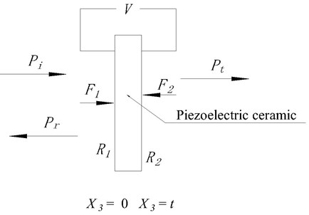
The arrangement of the single layer piezoelectric material is shown in Fig. 1.
Fig. 1The arrangement of the single layer piezoelectric material
2.1. Theoretical method
Several authors have presented work on the following topics: the derivation of the relation between normal forces on opposite faces of a thin piezoelectric material, the velocities of those faces, the voltage across and current through the piezoelectric material. Consider a piezoelectric material, which consists of a non-conducting piezoelectric layer of thickness much smaller than the dimensions of its faces, each of area . Denoting rectangular coordinates by , we define the axis normal to the faces of the piezoelectric material so that its thickness extends from (face 1) to (face 2).
For harmonic electric and/or acoustic excitation at angular frequency , we represent (1) all time-dependent quantities by the usual product of constant complex amplitude and (2) a time-dependent exponential. For example, at time the force on face 1 of the piezoelectric material is , where is the complex amplitude of that force. Thus we define and () as complex amplitudes of the normal forces and velocities of the piezoelectric material faces. We also define and as the complex amplitudes of the voltage across and current into the piezoelectric material. The sign conventions of these quantities are indicated in Fig. 1.
The relation between the complex amplitudes described above can be found using the fact that for . The elastic stress and strain, and the electric displacement and field intensity must satisfy the following: the usual mechanical laws of motion, Maxwell's equations, and the constitutive piezoelectric equations for the piezoelectric material. The interaction between these fields depends on the orientation of the symmetry directions of the material relative to the piezoelectric material faces. Let us assume that the material is isotropic in the direction and is polarized in the direction. If field disturbances are limited to the direction, they may be related using only the elements , , and of the elastic stiffness, piezoelectric stress constant, and dielectric impermissibility matrices. As a result of these assumptions, one obtains [6]:
In the above, is the velocity of longitudinal elastic (acoustic) waves traveling in the thickness direction of the piezoelectric material. is the density of the piezoelectric material, and is the acoustic number.
If we set , the electrical impedance of the air-loaded piezoelectric material may be obtained from Eqs. (1)-(3). The result is:
The material parameters , , and can thus be obtained by fitting Eq. (4) to measurements of electrical impedance versus frequency.
Suppose the above piezoelectric material separates two semi-infinite media of specific acoustic impedance and bounded by face 1 and 2, respectively. If a plane acoustic sound wave is normally incident on face 1, the net force results from the superposition of the incident and reflected sound waves, while is due to the transmitted sound wave. Letting , and be the complex pressure amplitudes of the incident, reflected and transmitted sound waves, respectively, we have:
Insertion of Eq. (5)-(8) into Eq. (1)-(3) yields:
In the above, , and is the specific acoustic impedance of the piezoelectric material.
In Eq. (9)-(11) is the complex amplitude of the current density into face 1 of the piezoelectric material.
Eq. (9)-(11) are simultaneous equations relating the complex amplitudes , , , and of five sigmoidally varying quantities. If two of these amplitudes are specified, the equations may be solved for the remaining three. If is set to desired incident sound wave amplitude and , thus we can have:
where , , , , , , , , are thickness, density, elastic coefficient, dielectric constant, and coupling constant of the piezoelectric material, respectively.
2.2. Electro-acoustic analogy method
The structure of the piezoelectric material used in this paper is shown in Fig. 2.
In the Fig. 2, is the thickness of the piezoelectric material. , are the vibration velocity in the direction of thickness. , are force press on the piezoelectric material. is voltage. According to the structure of the piezoelectric material, the equivalent circuit figuration is attained and shown in Fig. 3.
Fig. 2Structure of the piezoelectric ceramic
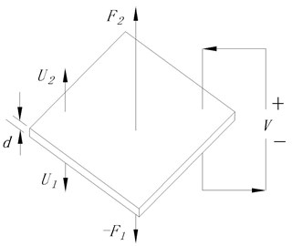
Fig. 3The equivalent circuit figuration
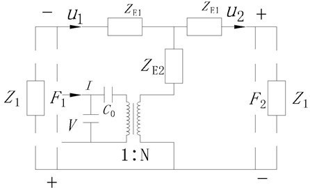
In the Fig. 3, , , , , , , , , are thickness, density, elastic coefficient, dielectric constant, and coupling constant of the piezoelectric material, respectively. The following equations can be derived according to the electro circuit theory:
According to the Eq. (5)-(8) and the Eq. (15)-(17), the following equations yield:
In the Eq. (18)-(20), there are five complex amplitudes . If two of these amplitudes are specified, the equations may be solved for the remaining three. For example, if is set to desired incident wave amplitude and is set to zero, the transformed equations read:
From the Eq. (21)-(23), the voltage of the piezoelectric material is attained:
According to the Eq. (24), the voltages applied on the piezoelectric material can make the reflected wave be zero and the aim of active absorption is gained.
According to the Eq. (12)-(14) and Eq. (24), the calculated results are the same, thus denote that the methods are correct and applicable.
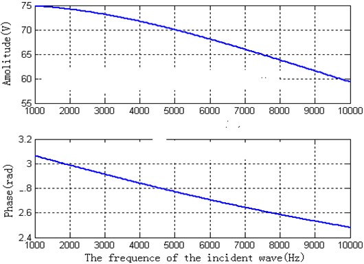
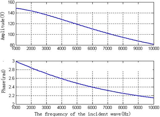
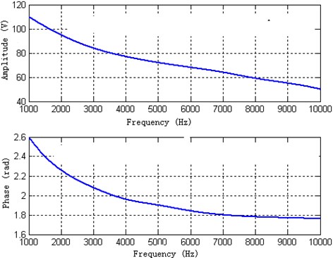
The density of the air is . The propagation velocity of sound wave in the air is . The density, the propagation velocity of sound wave in the piezoelectric material, and the dielectric constant of the piezoelectric material, respectively, are , , . The diameter of the piezoelectric material is and the thickness is . If the amplitude of the incidence wave is 1.00 Pa, the theoretical calculated amplitude and phase of the piezoelectric material, according to the Eq. (24), are shown in Fig. 4.
Fig. 4The theoretical calculated amplitude and phase of the piezoelectric ceramic
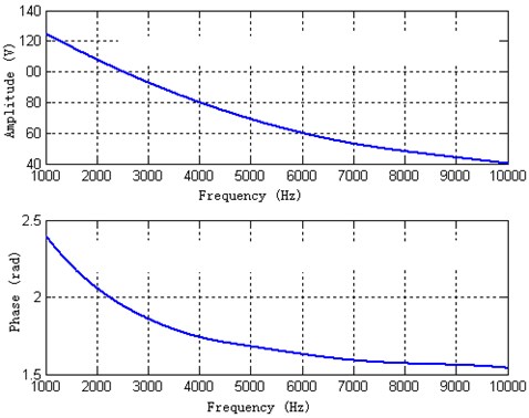
For the same piezoelectric material, the thickness is . If the amplitude of the incidence wave is 1.00 Pa, the theoretical calculated amplitude and phase of the piezoelectric material, according to the Eq. (24), are shown in Fig. (5).
Fig. 5The theoretical calculated amplitude and phase of the piezoelectric ceramic
For the same piezoelectric material, the thickness is . If the amplitude of the incidence wave is 1.00 Pa, the theoretical calculated amplitude and phase of the piezoelectric material according to the Eq. (24) are shown in Fig. (6).
Fig. 6The theoretical calculated amplitude and phase of the piezoelectric ceramic
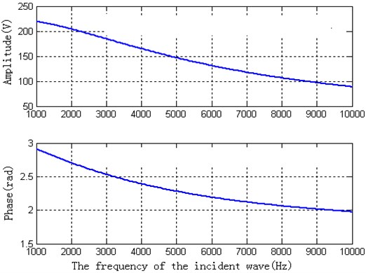
According to the Fig. 4-6, the conclusion can be drawn:
(1) For the piezoelectric material of the same thickness, the amplitude and the phase of the voltage are diminished when the incident frequency is added.
(2) For the same frequency of the incident wave, the amplitude of the voltage is added and the phase is diminished when the thickness of the piezoelectric material is added.
3. Double layer piezoelectric materials
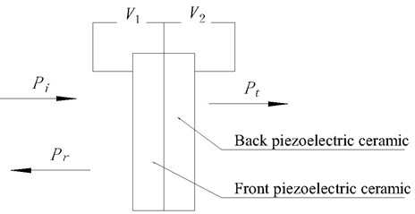
The arrangement of the double layer piezoelectric materials is shown in Fig. 7.
Fig. 7The arrangement of the double layer piezoelectric materials
3.1. Theoretical method
We now consider the piezoelectric ceramic, which consists a sandwich of two piezoelectric layers of the type described above, with face 2 of one layer fixed to face 1 of the other layer. For each layer a set of equations equivalent to Eq. (1)-(3) may be written. And yet, in order to allow for different material properties and thicknesses, we subscript the characteristic quantities of the layer “1” and “2”. We now have the additional boundary conditions and the forces and velocities of the two surfaces in contact are equal. The result of this boundary condition is a set of equations relating seven complex amplitudes, i.e.:
Expressions for the coefficients are given in the Appendix.
Equations (25)-(28) play a similar role for the double piezoelectric ceramic as Eqs. (9)-(11) for the single layer, i.e., they relate the complex amplitudes , , , , , and to the complex coefficients . In this case, for example, if we set to a desired incident wave amplitude and , according to the Equation (1)-(3) and the Equation (5)-(8), the following formula can be obtained:
where , , , , , , , , .
3.2. Electro-acoustic analogy method
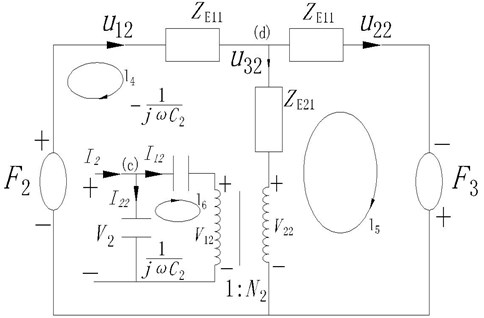
According to the structure of the piezoelectric ceramic, the equivalent circuit figuration of the front piezoelectric ceramic is attained and shown in Fig. 8.
Fig. 8The equivalent circuit figuration of the front piezoelectric ceramic
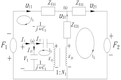
In the Fig. 8, , , , , , , , , are thickness, density, elastic coefficient, dielectric constant, and coupling constant of the front piezoelectric ceramic, respectively. The following equations can be derived according to the electro circuit theory:
The equivalent circuit figuration of the back piezoelectric ceramic is shown in the Fig. 9.
Fig. 9The equivalent circuit figuration of the back piezoelectric ceramic
In the Fig. 9, , , , , , , , , are thickness, density, elastic coefficient, dielectric constant, and coupling constant of the back piezoelectric ceramic, respectively. The following equations can be derived according to the electro circuit theory:
According to the Equations (36)-(38), the following equations yield:
According to the Eq. (39)-(42), the voltages applied on the piezoelectric ceramics can make the reflected wave and transmission wave be zero. The aim of active absorption and active isolation is gained.
According to the Eq. (29)-(32) and Eq. (39)-(42), the calculated results are the same, thus denote that the methods are correct and applicable.
Fig. 10The theoretical calculated amplitude and phase of the front piezoelectric ceramic
The front and back of piezoelectric ceramic are the same. The density, the acoustic impedance, the dielectric constant, and coupling constant of the piezoelectric ceramics, respectively, are , , , . The diameter of the piezoelectric ceramic is and the thickness is . If the amplitude of the incidence wave is 1.00 Pa, the theoretical calculated amplitude and phase of the front piezoelectric ceramic according to the Eq. (41)-(44) are shown in Fig. 10.
The theoretical calculated amplitude and phase of the back piezoelectric ceramic according to the Eq. (41)-(42) are shown in Fig. 11.
Fig. 11The theoretical calculated amplitude and phase of the back piezoelectric ceramic
4. Conclusion
In this paper, two methods – the theoretical method and the electro-acoustic analogy method – are used in order to compare the driving voltage applied across the single and the double layer of active sound surfaces of piezoelectric material. Computational results indicate that the proposed theoretical models are correct and applicable in practical implementations.
References
-
Ting R. Y. Characterization of the properties of underwater acoustical materials. J. Acoust. Soc. Am., Vol. 86, Issue 21, 1989.
-
Rittenmyer K. M., Dubbelday P. S. Determination of the piezoelectric properties composite materials by laser Doppler velocimetry. J. Acoust. Soc. Am., Vol. 88, Issue 114, 1990.
-
Ting R. Y. Recent developments in piezoelectric composites for transducer applications. J. Acoust. Soc. Am., Vol. 85, Issue 60, 1989.
-
Geil F. G., Ting R. Y. Application of piezoelectric composite for large area hydrophone arrays. J. Acoust. Soc. Am., Vol. 84, Issue 68, 1988.
-
Rittenmyer K. M. Temperature dependence of the electromechanical properties of ceramic polymer composite materials for hydrophones application. J. Acoust. Soc. Am., Vol. 83, Issue 81, 1988.
-
Berlincourt D. A., Curran D. R., Jaffe H. Piezoelectric and piezomagnetic materials and their function in transducer. In Physical Acoustics: Principles and Methods, Academic, New York, 1964, p. 169-270.
About this article
This work is supported by National Nature Science Foundation of China (Grant No. 50075029).
