Abstract
An effective method for identifying and diagnosing the concurrent fault combined by two or more single faults is yet to be further developed because most existing approaches focus on single faults. On the other hand, rotor-bearing system is an important part of rotating machinery. Therefore a new fault identification and diagnosis method based on wavelet packet transform (WPT) and zero space classifiers is presented in this paper. Firstly, the vibration signals collected from the rotor-bearing system are decomposed into several time-frequency compositions by WPT. Then the appropriate composition characterizing fault signatures is selected to extract features for constructing zero space classifiers. Finally, the effectiveness of the proposed method is demonstrated by an experiment carried out on a machinery fault simulator. The experimental results show that the proposed approach is feasible and effective to identify and diagnose the concurrent faults in a rotor-bearing system.
1. Introduction
Rotor-bearing system is an important part of rotating machinery. In this system, bearing failure may cause performance deterioration of overall machine and even lead to fatal machine breakdowns or disastrous accidents [1]. On the other hand, rotor unbalance is a frequent fault in a rotor-bearing system, which may be also with great potential dangerous [2]. Thus it is significant to construct an effective fault identification and diagnosis method to reduce unscheduled downtime and economical loss of rotating machinery with a rotor-bearing system.
As vibration signals usually carry rich information about mechanical conditions, vibration analysis has received extensive and intensive research for fault diagnosis [3-5]. Many useful signal processing methods have been proposed to analyze vibration signals for mechanical fault diagnosis. Fast Fourier transform (FFT) is the simplest frequency analysis method proposed in 1971 [6]. Theoretically, bearing faults can be diagnosed by analyzing the frequency compositions with FFT. However, the vibration signals collected from a rotor-bearing system usually carry noise and other vibration components, thus the primitive FFT will be helplessness in extracting the overwhelmed remarkable information for fault diagnosis [7]. In order to solve this problem, time-frequency analysis techniques such as short-time Fourier transform (STFT) [8], Wigner-Ville distribution (WVD) [9, 10], continuous wavelet transform (CWT) [11-13], discrete wavelet transform (DWT) [14, 15] and wavelet packet transform (WPT) [16, 17] have been put forward for fault diagnosis. WPT, by contrast, has better frequency resolution in the whole time-frequency plane and is more suitable to process the non-stationary and non-linear vibration signals for fault diagnosis [17].
To date, many methods have been developed for fault diagnosis of rotating machinery with vibration analysis technique. Unfortunately, most of them focused on single faults. The problem becomes rather complex when different faults act themselves in a combined manner which is called as concurrent fault [18]. Moreover, these concurrent faults are also difficult to be described by an accurate model with mathematical method [19]. Therefore, few studies have focused on the diagnosis of concurrent faults. The diagnosis work of three single faults and a combined defect was studied for bearings by using CWT [11, 12]. Prabhakar et al. [15] proposed a method based on DWT for the detection of a multiple fault (defects both on inner race and outer race). Zarei and Poshtan [16] developed a method based on WPT and stator current analysis to detect the faults of two holes on the outer race and one hole on other bearing parts. In [20], these conditions combined by some single faults on inner race, outer race and ball were successfully identified with wavelet analysis and hidden Markov model. Saimurugan et al. [21] introduced a fault diagnosis method based on decision tree and support vector machines (SVM) for multi-component faults which were combinations of various shaft faults and bearing faults. Jing and Meng [22] employed blind source separation technique to separate the vibration features produced by multi-faults such as unbalance and impact-rub, crack and impact-rub existing in a rotor. In [23] and [24], the multiple faults in a rotor system were identified by model-based analysis methods. Although above methods were able to deal with concurrent fault diagnosis, they assumed that the failure of mechanical system was a single fault (the concurrent fault regarded as an isolated status like a single fault). As the coupling between the rotor and bearing, it is difficult to develop an accurate mathematical model for concurrent faults of a rotor-bearing system. Meanwhile a model is also just suitable for some specific concurrent faults.
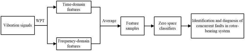
In this study, a new method based on WPT and zero space classifiers is proposed for the identification and diagnosis of concurrent faults in a rotor-bearing system. The flow chart of the proposed method is shown in Figure 1. Firstly, with WPT used, the collected vibration signals are decomposed into several time-frequency compositions. Then the appropriate composition is selected for features in time domain and frequency domain. Finally, zero space classifiers are constructed to identify and diagnose the concurrent faults in a rotor-bearing system. The rest of this paper is structured as follows. Section 2 introduces a WPT based feature extraction method. The implementation of the proposed method is given in section 3. In section 4, an experiment is carried out to illustrate the effectiveness of the proposed approach. Finally, the conclusion of this paper is made in section 5.
Fig. 1Flow chart of the proposed method
2. Feature extraction
2.1. Wavelet packet transform
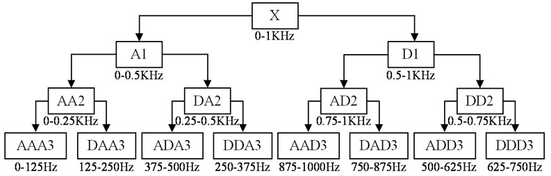
In wavelet transform (WT), the lost information of the low frequency part will be acquired by the high frequency part in each decomposition layer and the frequency resolution of wavelet decomposition decreases with the frequency increases. However WPT has a better frequency resolution because both the low-pass and high-pass are split in all layers. On the other hand, WPT splits not only details (D) but also approximations (A), which means that different faulty information of various frequency bands can be extracted from original vibration signals [25, 26]. Therefore WPT is more suitable for complicated signal processing than WT. Figure 2 shows a three-level WPT, in which the vibration signal is decomposed into various low and high frequency components.
Fig. 2A WPT tree with three levels
2.2. Characteristic damage frequency (CDF)
A normal bearing will move itself smoothly until a defect appears. For a bearing fault, the vibration signal contains its own unique periodic impulse composition called as characteristic damage frequency (CDF). The CDFs of bearings are determined by shaft rotational speed, fault location and bearing dimensions, and which can be represented as [3, 4]:
where , , and are the CDFs of cage fault, outer race fault, inner race fault and ball fault, respectively; and are the ball and pitch diameter, respectively; is the number of ball elements; and is the angle of the load from the radial plane.
2.3. WPT based feature extraction
When a fault appears, the amplitude and distribution of its vibration signal are different from those of normal in time domain and the energies of CDFs also will change markedly in frequency domain [27]. A feature extraction method based on WPT is prospected in this subsection. In this method, the appropriate decomposition, including useful information, i. e., the compositions of bearing CDFs and mechanical rotating frequency are decomposed into one node in which the other frequency compositions should be as few as possible, is selected for feature extraction.
Seventeen time-domain feature parameters and twelve frequency-domain feature parameters shown in Table 1 are selected for features. Feature parameters – indicate the vibration amplitude and energy in time domain. Feature parameters – represent the time series distribution of the signal in time domain. Feature parameter delegates the vibration energy in frequency domain. Feature parameters and describe the convergence of the spectrum power. Features parameters show the position change of the main frequencies [27, 28]. Vibration signals obtained from a rotor-bearing system usually contain noise interference, so the values of the same feature parameter extracted at different time may be various, which may reduce the accuracy of concurrent fault identification and diagnosis. To solve this problem, the feature sample is averaged from these extracted features.
Table 1The feature parameters
Time domain feature parameters | |||
Frequency domain feature parameters | |||
where is a vibration signal with data points, is a spectrum series with data points and is the frequency value of the th spectrum line. | |||
3. The proposed method for concurrent fault diagnosis
In [29], the feature vectors are projected onto the defined zero space vectors to obtain residual signals for estimating fault severity. Feature decoupling vector, similar to zero space vector, was firstly proposed for fault diagnosis of bearings with simple algebraic computation and decision logic [30]. It has been demonstrated that the feature decoupling vector based fault diagnosis method is faster than artificial neural network and SVM in fault diagnosis. Therefore, in our work, zero space classifiers are constructed for identifying and diagnosing concurrent faults.
For a fault diagnosis method, the first step is to diagnose whether a machine works properly or not, and the next is to identify the types of failures. Therefore the proposed method includes two parts: monitoring of normal condition and identification of concurrent faults. Before constructing the proposed method, we assume that:
and:
where is the average value of the th feature parameter of these extracted samples under the th mechanical conditions; and is the total number of mechanical conditions and feature parameters, respectively.
Part 1: monitoring of normal condition
In this part, Euclidean distance is applied for the monitoring of normal condition. is defined as the Euclidean distance of the feature sample to the center of normal condition, and which is calculated by:
where , equal to in the matrix , is the center of normal condition.
Set:
where and are defined as the condition isolation parameter (CIP) and threshold of a rotor-bearing system under normal condition, respectively. The threshold is calculated by:
where and are the mean and standard deviation of these Euclidean distances of feature samples under normal condition to .
In Eq. (5), means that the rotor-bearing system is under normal condition, and means that the rotor-bearing system is under abnormal condition.
Part 2: identification of concurrent faults
This part is mainly to identify the fault type when the rotor-bearing system is under a concurrent fault. As the feature samples of normal condition are no use for the fault identification, the normal condition is eliminated from the different kinds of conditions.
Define:
where is defined as the basic state set, is defined as the derivative state set; to are kinds of single faults. At the same time, and satisfy:
where are types of concurrent faults each one is combined by two or more of the single faults in .
Assume that the intersection of a concurrent fault and any one of its combined single faults is not an empty set. For instance, if is combined by and , then we can get:
Set:
where .
Denote the left zero space of as that is where is the matrix with the corresponding centers of these mechanical conditions in . Select a vector from the left zero space as the zero space vector which satisfies:
where and .
Then all the zero space vectors of types of single faults in can be written as:
Set:
where is defined as the residual signal implying the information about the th single fault.
According to the discussion above, the residual signal is the projection of a feature sample on . If the rotor-bearing system is under the th fault condition within the kinds of single faults, only when . Theoretically, this rule can be used for concurrent fault identification. However, the residual signal, originally being zero, will be nonzero due to noise interference. Thus new rules should be constructed to improve the accuracy of concurrent fault identification, and which are defined as:
where and are defined as the CIP and threshold of the th single fault in , respectively. The threshold is calculated by:
where is a constant and is a series of residual signals calculated from the feature samples of these single faults in except the th one.
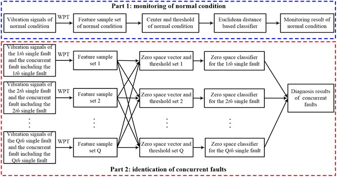
In Eq. (14), means that the th single fault occurs, and means that the th single fault does not occur. The above-described implementation process is shown in Figure 3.
Fig. 3Implementation process of the proposed method
4. Experiment validation and analysis
4.1. Experimental set up
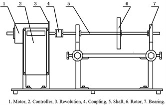
An experiment is carried out to validate the effectiveness of the proposed method on a machinery fault simulator shown in Figure 4. In this experiment, a normal bearing without any defect is located in the inboard bearing housing closer to the motor. A series of test bearings with various defects are located in the outboard bearing housing farther to the motor in turn to simulate these faults: (1) fault in inner race; (2) fault in outer race; (3) fault in ball and (4) faults in inner race, outer race and ball at the same time. The place, middle of the shaft between the inboard bearing housing and outboard bearing housing, is mounted a rotor disk. The rotor unbalance fault is achieved by adding a screw in one of the tapped holes in the rotor disk edge.
Fig. 4Test bench: a) experimental system and b) its schematic model
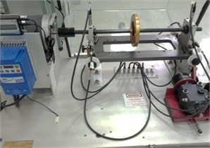
(a)
(b)
Other experimental setups contain several ICP acceleration sensors fixed on the bearing housings and a data acquisition system. The rotating speed of this simulator is set at 1198RPM with a motor controlled by a controller. The simulated conditions in this experiment are shown in Table 2, in which S1 is normal condition, S2-S5 represent single faults and S6-S10 mean concurrent faults. Ten data sets are collected from the test beach under above-noted conditions at a constant sampling frequency of 2000 Hz. Figure 5 shows the primordial vibration signals and corresponding FFT spectrums of the conditions S2, S3 and S6. Observation of these plots in Figure 5 reveals that the original vibration signal of S6 is particular similarity to those of both S2 and S3, i. e., some compositions belonging to S2 or S3 manifest themselves in a nonlinear combined manner in S6. This is more obvious in their FFT spectrums.
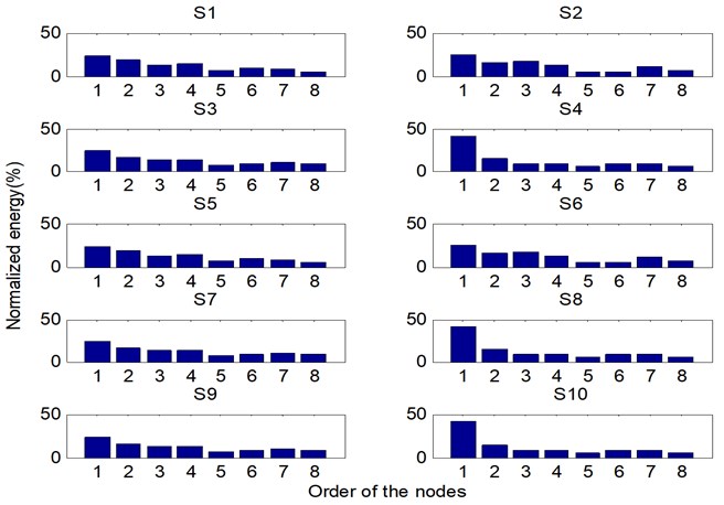
According to Eq. (1) and the user operation manual of the machinery fault simulator, the CDFs of bearings are not more than 100 Hz. Further analysis of Figure 2 shows that the compositions of bearing CDFs and rotational frequency are included in the first node of WPT. Figure 6 shows the normalized energies of the nodes in the third level of the WPT tree, in which – axis shows the number of the nodes and – axis signifies amplitude of energies in unit of percentage (%). The first node with the greatest energy also reveals that it includes the most useful information for fault identification and diagnosis. Therefore the first node is selected to further process for feature samples and each element of a feature sample is averaged from 100 values of the corresponding feature parameter. For each condition, a total of 120 feature samples are extracted, in which 100 ones for constructing the proposed method and the other 20 ones for testing.
Table 2The simulated conditions
Identifier | Description | Identifier | Description |
S1 | Normal condition | S6 | Fault combined by S2 and S3 |
S2 | Rotor unbalance | S7 | Fault combined by S2 and S4 |
S3 | Fault in the inner race | S8 | Fault combined by S2 and S5 |
S4 | Fault in the out race | S9 | Fault combined by S3, S4 and S5 |
S5 | Fault in the rolling element | S10 | Fault combined by S2, S3, S4 and S5 |
Fig. 5Vibration signals and FFT spectrums of these conditions: S2, S3 and S6
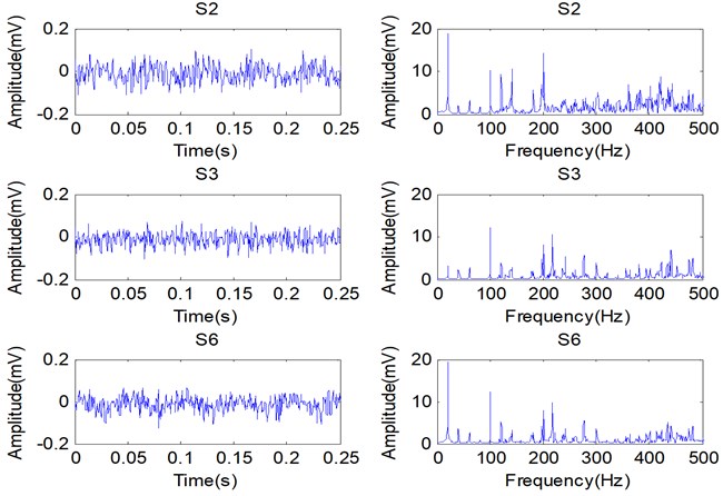
Fig. 6The normalized energies of the nodes in the third level of WPT
4.2. Results and discussion
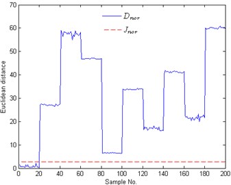
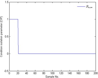
Figure 7(a) shows the corresponding threshold and Euclidean distances of the 200 test samples to the center of normal condition. As shown in this graph, the Euclidean distances of these test samples with No. 1-20 are smaller than those of these test samples with No. 21-200. When comparing these Euclidean distances and the threshold plotted in Figure 7(a), it is obviously that only these Euclidean distances of the test samples with No. 1-20 are smaller than the threshold. The corresponding CIPs are also calculated by Eq. (5) and shown in Figure 7(b) with No. 1-20. According to Figure 7 (a) and (b), it is obviously that the test samples with No. 1-20 belong to the normal condition and the other test samples belong to the abnormal condition. Therefore the task of the monitoring normal condition, shown in Figure 3, can be performed effectively.
Fig. 7Monitoring results of normal condition: a) Euclidean distances and b) CIPs of the 200 test samples; Dnor is the Euclidean distance of a test sample to the center of normal condition; Jnor and Rnor are the threshold and the CIP of normal condition, respectively
(a)
(b)
When a concurrent fault appears, the next work is to identify which fault type of the rotor-bearing system is under. Further analysis of these conditions in Table 2 shows that faults are all combined by one or more of these single faults: rotor unbalance, inner race fault, outer race fault and ball fault. At the same time, we can get . Therefore total 4 zero space classifiers should be constructed for identifying these conditions in .
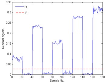
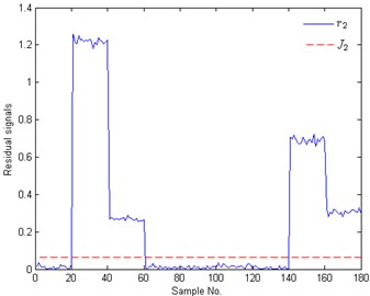
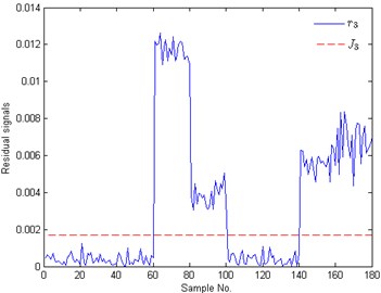
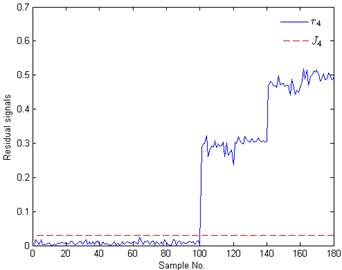
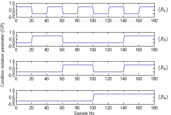
In Figure 8(a)-(d), solid lines represent residual signals of test samples and dotted lines signify the corresponding thresholds. The CIPs of Figure 8 are shown in Figure 9, where the value ‘1’ means that the corresponding fault appears. In Figure 8 and Figure 9, the plots with No. 1-20, 21-40, 41-60, 61-80, 81-100, 101-120, 121-140, 141-160, 161-180 are the test results of these test samples under S2, S3, S6, S4, S7, S5, S8, S9 and S10, respectively. For these test samples with No. 1-20, the case that the residual signals are bigger than the threshold only appears in Figure 8(a), i.e., and with sample No. 1-20 only when . According to Eq. (14), we can draw a conclusion that the test samples with No. 1-20 belong to rotor unbalance fault. In the same way, the conditions of these samples with No. 21-40, 61-80 and 101-120 are identified as inner race fault, outer race fault and ball fault, respectively. These test results all accord with the fact. When analyzing the results of the test samples with No. 41-60, we can find that and only when . Therefore this concurrent fault combined by rotor unbalance fault and inner fault is successfully isolated. The rest test results show that the concurrent faults S7-S10 are also all successfully isolated. The isolation results indicate that the proposed method can identify and diagnose these concurrent faults with high accuracy when they are regarded as combination conditions.
According to the above analysis, it can be seen that the proposed method can effectively identify the concurrent faults in a rotor-bearing system. Besides, some comparative studies such as back-propagation (BP) neural network and radial basis function (RBF) neural network for diagnosing concurrent faults also have been carried out. In almost all of the existing diagnosis methods, the concurrent fault was regarded as an independent failure state just like a single fault. Therefore ten classes will be identified by BP or RBF network. The test samples used in Figure 7 and Figure 8 are also successful diagnosed by BP and RBF network. Unfortunately, BP and RBF need more time than the proposed method. Training BP and RBF with 1000 samples need 3.455160 and 1.193935 s, but our method just requires 0.001895 s for constructed the Euclidean distance based classifier and the zero space classifiers with the same samples. The cost times of BP and RBF in testing stage are 0.012285 and 0.065949 s, respectively. However our work just needs 0.002911 s to do the same testing work. What is more, the testing time of the part 2 shown in Figure 3 is just 0.000396 s. It can be seen that the proposed method is more time-saving than BP and RBF, whether in design stage or in testing stage.
Fig. 8Identification results of concurrent faults: a) to b) are the test results of the 1th to 4th zero space classifier, respectively; ri and Ji means the residual signals and the thresholds of the ith zero space classifier
(a)
(b)
(c)
(d)
Fig. 9The corresponding CIPs of these test samples shown in Fig. 8
5. Conclusion
In this paper, a new method based on wavelet packet transform (WPT) and zero space classifiers was presented to identify and diagnose the concurrent faults in rotor-bearing system for improving the reliability of rotating machinery. In this method, the non-stationary and non-linear vibration signals were decomposed into several time-frequency compositions by using a three-level WPT. The first component in the third level of WPT was selected for features in time-domain and frequency-domain by analyzing the bearing CDFs and the energy distribution among the decomposition results. By observing the FFT spectrum, it can be see that the concurrent fault was a nonlinear combination of two or more single faults. Usually, the values of the same feature parameter obtained from the vibration signal at different time were various because of the noise interference, which may reduce the accuracy of fault diagnosis. To overcome this problem, the values of the used feature parameters were averaged for feature samples. In order to identify and diagnose the concurrent faults more convenient, the concurrent fault was no longer regarded as a dependent state just like a single fault and zero space classifiers were constructed to isolate the single faults building a concurrent fault. The experimental results showed that the new fault diagnosis method can successfully monitor normal condition and identify concurrent faults by isolating their compositions into several single faults. On the other hand, the proposed method needs litter computation load than BP and RBF for the same task of concurrent fault identification and diagnosis in a rotor-bearing system.
References
-
Yang Y., Wang H., Cheng J., Zhang K. A fault diagnosis approach for roller bearing based on VPMCD under variable speed condition. Measurement, Vol. 46, Issue 8, 2013, p. 2306-2312.
-
Xu B. G. Intelligent fault inference for rotating flexible rotors using Bayesian belief network. Expert Systems with Applications, Vol. 39, Issue 1, 2012, p. 816-822.
-
Cocconcelli M., Bassi L., Secch C., Fantuzzi C., Rubini R. An algorithm to diagnose ball bearing faults in servomotors running arbitrary motion profiles. Mechanical Systems and Signal Processing, Vol. 27, 2012, p. 667-682.
-
Zarei J. Induction motors bearing fault detection using pattern recognition techniques. Expert Systems with Applications, Vol. 39, Issue 1, 2011, p. 68-73.
-
Zhu K. H., Song X. G., Xue D. X. Incipient fault diagnosis of roller bearings using empirical mode decomposition and correlation coefficient. Journal of Vibroengineering, Vol. 15, Issue 2, 2013, p. 597-603.
-
Corinthios M. J. A fast Fourier transform for high-speed signal processing. IEEE Transactions on Computers, Vol. 20, 1971, p. 843-846.
-
Zarei J., Poshtan J. An advanced Park’s vectors approach for bearing fault detection. Tribology International, Vol. 42, Issue 2, 2008, p. 213-219.
-
Brotherton T. B., Pollard T. Applications of time-frequency and time-scale representations to fault detection and classification. Proceedings of the IEEE Signal Processing International Symposium on Time-Frequency and Time-Scale Analysis, Orlando, 1992, p. 95-98.
-
Wu J. D., Chiang P. H. Application of Wigner-Ville distribution and probability neural network for scooter engine fault diagnosis. Expert Systems with Applications, Vol. 36, Issue 2, 2009, p. 2187-2199.
-
Zhou Y., Chen J., Dong G. M., Xiao W. B., Wang Z. Y. Wigner-Ville distribution based on cyclic spectral density and the application in rolling element bearings diagnosis. Proceedings of the Institution of Mechanical Engineers, Part C: Journal of Mechanical Engineering Science, Vol. 225, Issue C12, 2011, p. 2831-2847.
-
Kankar P. K., Sharma S. C., Harsha S. P. Fault diagnosis of ball bearings using continuous wavelet transform. Applied Soft Computing, Vol. 11, Issue 2, 2010, p. 2300-2312.
-
Kankar P. K. Sharma S. C. Harsha S. P. Rolling element bearing fault diagnosis using autocorrelation and continuous wavelet transform. Journal of Vibration and Control, Vol. 17, Issue 14, 2011, p. 2081-2094.
-
Ashory M. R., Masoumi M., Jamshidi E., Khalili B. Using continuous wavelet transform of generalized flexibility matrix in damage identification. Journal of Vibroengineering, Vol. 15, Issue 2, 2013, p. 512-419.
-
Abad M. R. A. A., Ahmadi H., Moosavian A., Khazaee M., Kohan M. R., Mohammadi M. Discrete wavelet transform and artificial neural network for gearbox fault detection based on acoustic signals. Journal of Vibroengineering, Vol. 15, Issue 1, 2013, p. 459-463.
-
Prabhakar S. Mohanty A. R. Sekhar A. S. Application of discrete wavelet transform for detection of ball bearing race faults. Tribology International, Vol. 35, Issue 12, 2002, p. 793-800.
-
Zarei J., Poshtan J. Bearing fault detection using wavelet packet transform of induction motor stator current. Tribology International, Vol. 40, Issue 5, 2007, p. 763-769.
-
Zhong G. S., Ao L. P., Zhao K. Influence of explosion parameters on wavelet packet frequency band energy distribution of blast vibration. Journal of Central South University, Vol. 19, Issue 9, 2012, p. 2674-2680.
-
Zio E., Baraldi P., Gola G. Feature-based classifier ensembles for diagnosing multiple faults in rotating machinery. Applied Soft Computing, Vol. 8, Issue 4, 2008, p. 1365-1380.
-
Liu J. B., Wang X. Q. Vibration pattern recognition and classification of electric generator in power system using wavelet analysis. Proceedings of the 27th Chinese Control Conference, Kunming, 2008, p. 34-37.
-
Purushotham V., Narayanan S., Prasad SAN. Multi-fault diagnosis of rolling bearing elements using wavelet analysis and hidden Markov model based fault recognition. NDT & E International, Vol. 38, Issue 8, 2005, p. 654-664.
-
Saimurugan M., Ramachandra K. I. N., Sugumaran V., Sakthivel N. R. Multi component fault diagnosis of rotational mechanical system based on decision tree and support vector machine. Expert Systems with Applications, Vol. 38, Issue 4, 2011, p. 3819-3826.
-
Jing J. P., Meng G. A novel method for multi-fault diagnosis of rotor system. Mechanism and Machine Theory, Vol. 44, Issue 4, 2009, p. 697-709.
-
Bachschmid N., Pennacchi P., Vania A. Identification of multiple faults in rotor systems. Journal of Sound and Vibration, Vol. 254, Issue 2, 2002, p. 327-366.
-
Bachschmid N., Pennacchi P. Multiple fault identification method in the frequency domain for rotor systems. Shock and Vibration, Vol. 9, Issue 4-5, 2002, p. 203-215.
-
Ekici S., Yildirim S., Poyraz M. Energy and entropy-based feature extraction for locating fault on transmission lines by using neural network and wavelet packet decomposition. Expert Systems with Applications, Vol. 34, Issue 4, 2008, p. 2937-2944.
-
Tan J., Chen X. S., Du M., Zhu K. A novel internet traffic identification approach using wavelet packet decomposition and neural network. Journal of Central South University, Vol. 19, Issue 8, 2012, p. 2218-2230.
-
Lei Y. G., He Z. J., Zi Y. Y., Hu Q. Fault diagnosis of rotating machinery based on multiple ANFIS combination with Gas. Mechanical Systems and Signal Processing, Vol. 21, Issue 5, 2007, p. 2280-2294.
-
Shen Z. J., Chen X. F., Zhang X. L., He Z. J. A novel intelligent gear fault diagnosis model based on EMD and multi-class TSVM. Measurement, Vol. 45, Issue 1, 2012, p. 30-40.
-
Jiang F., Li W., Wang Z. Q., Zhu Z. C. Fault severity estimation of rotating machinery based on residual signals. Advances in Mechanical Engineering, Vol. 2012, 2012, p. 1-8.
-
Li W., Jiang F., Zhu Z. C., Zhou G. B., Chen G. A. Fault diagnosis of bearings based on a sensitive feature decoupling technique. Measurement Science and Technology, Vol. 24, Issue 3, 2013, p. 1-12.
About this article
This work is supported by the National Natural Science Foundation of China (51275513), the Program for Changjiang Scholars and Innovative Research Team in University-PCSIRT (IRT1292), the Project Funded by the Priority Academic Program Development of Jiangsu Higher Education Institutions (PAPD).
