Abstract
Planetary Drive with Small Teeth Number Difference (PDSTND) is widely utilized in industry for its advantages including large transmission ratio, huge torque and high efficiency. However, interference can easily occur due to the small teeth number difference between annulus and planetary gear, which can be solved by modification. Besides, noise and vibration are still the remained problems to influence its working performance. In order to discover the interaction of modification coefficient and vibration, a nonlinear dynamic model is established by using Lagrange equation and solved by the fourth-order Runge-Kutta method. Modification coefficient, backlash and transmission error are used as the control parameters to investigate their effects on the dynamic characteristics of the system, by means of bifurcation diagrams, Poincaré maps, trajectories and frequency spectrums. The results show that the system turns into quasi-periodic motion, and then alternates between period- ( 5, 6) and chaotic motion as modification coefficient increases. Moreover, the responses of backlash and transmission error to the system get more complex with increasing modification coefficient. The results can provide new theoretical basis for the design, manufacture and fault diagnosis of PDSTND.
1. Introduction
Planetary Drive with Small Teeth Number Difference (PDSTND) is widely applied in industry for its advantages including large transmission ratio, huge torque, small size and high efficiency. However, interference can easily occur because of the small teeth number difference between annulus and planetary gear, which will lead to the failure of PDSTND and can be solved by modification. Besides, the noise and vibration are still the remained problems, which not only deteriorate the working condition but also reduce the reliability and durability of machine systems. Therefore, it is necessary to study modification methodology and dynamic characteristics of PDSTND for prolonging lifetime and improving efficiency.
In the early 20th century, different modification methods and laws were developed to solve interference, the proposal of “closed graph” method represented the maturity of modification methodology until the 1950s [1]. Subsequently, the problem of the distribution of the sum of profile shift coefficients on each cylindrical gear was treated and recommended especially in standards for gearing optimization [2, 3], which were compared and discussed by Mirică [4].
In order to prolong life and reduce power loss, more relevant studies on gears mainly focused on both good tooth load capacity and efficiency. In early studies, the analyses and load calculation of PDSTND obeyed the ISO standards approximately [5-7]. Afterwards, Chen and Walton [8] studied optimum design of PDSTND. Shu [9] and Zhou [10] conducted studies on determination of load-sharing factor of PDSTND. Li [11] presented an effective method to solve contact analysis and calculate the loads distributed on teeth, pins and rollers. Besides, various methods had been presented to evaluate the local friction coefficient and efficiency [12-14], and these methods were compared incorporating modification coefficient by Baglioni [15].
Recently, a variety of mathematical models had been developed to investigate gear noise and vibration [16, 17]. With further research for the dynamic characteristics of PDSTND, more parameters were taken into consideration in the analysis of PDSTND. Time-varying stiffness, transmission error and backlash were analyzed as parametric excitation to study the effect of each to gearing system in [18-20]. Lumped parameter models were used to predict the free and forced vibration characteristics of the planetary gear sets [21-23], and finite element models were applied for complex analysis of the effects of design parameters on dynamic response [24, 25].
It is obvious that the previous studies on modification and dynamics are irrelevant. This present work aims to discover the interaction between modification coefficient and dynamics incorporating backlash and transmission error. A nonlinear dynamic model is proposed by using Lagrange equation and solved by the fourth-order Runge-Kutta method. Modification coefficient, backlash and transmission error are used as the control parameters to investigate their effects on the system, by means of bifurcation diagrams, Poincaré maps, trajectories and frequency spectrums.
2. Dynamic model of system
2.1. Nonlinear model
The object studied in this paper is the well-known KHV PDSTND used widely in industry, and the schematic diagram is shown in Fig. 1 [8], which consists of drive , carrier , annulus , planetary gear and load . Annulus is fixed on the housing, and other components are mounted on the flexible shafts supported by bearings.
In order to establish the dynamic model of the KHV shown in Fig. 1 efficiently, some assumptions are proposed as follows:
a) The stiffness of the supporting bearings for each rotating part is large enough to neglect the transverse displacement of each part, and only torsional displacement is considered.
b) Annulus is fixed on the housing; all displacements of annulus are not included.
c) The effect of friction caused by moving bearings is not taken into account.
d) The equal angular velocity mechanism in KHV is regarded as a flexible shaft with stiffness and damping.
Based on the above assumptions, the 4-DOF nonlinear dynamic model is established as shown in Fig. 2, and corresponding DOFs are rotations of drive , carrier , planetary gear and load .
Fig. 1The schematic diagram of the KHV
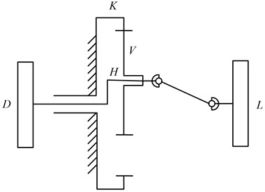
Fig. 2The dynamic model of the KHV
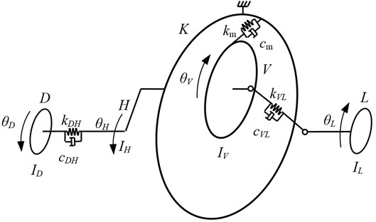
The angular displacement of each part is , , and respectively, meanwhile, the equivalent transverse displacements in the pressure line direction caused by rotational displacements are introduced to simplify the mathmatical model:
The following effects are calculated in the mathmatical model: inertia of drive , torsional stiffness and damping of input drive shaft, inertia of carrier , inertia of planetary gear , time-varying meshing stiffness and damping of the meshing teeth between annulus and planetary gear , torsional stiffness and damping of output drive shaft, inertia of load , backlash, transmission error, drive and load torque. The dynamic mathematical model can be derived by using Lagrange equation as follows:
where:
: the backlash function which will be given in section 3.4,
: the transmission error which will be given in section 3.5.
Due to the linear and nonlinear resilience in the system, the equation can not be solved by analytic solution. Therefore, relative displacements in the direction of pressure line are defined as follows:
Therefore, the set of simplified governing equations is obtained:
where
If a displacement vector is introduced:
the Eq. (4) can be given in the matrix form as:
where is the mass matrix, is the damping matrix, is the sitffness matrix, is the vector expression of the backlash nonlinearity in section 3.4 and is the vector expression of excitation.
2.2. Modification coefficient
In order to analyse the dynamic characteristics of the KHV, the structural parameters of the KHV are given in Table 1.
Table 1Structural parameters of the KHV
Parameters | Teeth number | Module (mm) | ha* | Facewidth (mm) |
30 | 3.5 | 0.8 | 20 | |
33 | 3.5 | 0.8 | 20 |
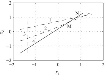
The closed graph of the system in Fig. 2 can be obtained and plotted in Fig. 3 based on the method in [26].
The lines in Fig. 3 are defined as follows: Line 1: limited line with 1; line 2: restrict line with no teeth profile interference; line 3: limited line with no shortcut of the gear; line 4: restrict line with equal meshing angle.
The points located on line 4 and in the region encompassed by the lines 1-3 are qualified for modification coefficient. (0.416, 0.601) and (0.835, 0.995) are two limited points. In order to simplify calculation, will take place of the coordinate pair in the following discussion.
Fig. 3Closed graph
2.3. Calculation of mesh stiffness
A method has been proposed for the meshing stiffness calculation of a spur gear pair [27], in which parabola is applied to fit the stiffness variation with time. The stiffness change for a single-tooth engagement is shown in Fig. 4.
Fig. 4Stiffness for a single-tooth engagement
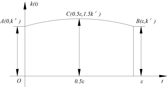
The stiffness of meshing point is 1.67 times as large as that of engaging-in point for inner gearing. The stiffness of engaging-in point , pitch point and meshing point are , and respectively, and
According to the ISO Standard [28], when where is the pressure angle, and are the gear and annulus modification coefficient respectively, the meshing stiffness in pitch point can be calculated by the following equation:
where is the teeth facewidth.
where “+”is used for inner gearing, “–”is used for external gearing, and are the quivalent teeth numbers.
The meshing stiffness expression is deduced by , , as follows:
where
The average meshing stiffness can be derived by integration:
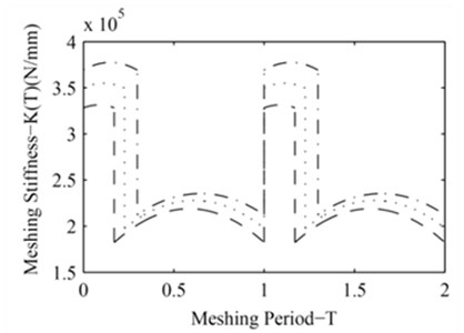
The time-varying meshing stiffness of the KHV for different is shown in Fig. 5.
Fig. 5The time-varying meshing stiffness of the KHV for different modification coefficient (: x1= 0.416, : x1= 0.626, : x1= 0.835)
2.4. Backlash
The backlash is inevitable in gear engagement due to the purpose for lubrication, machining error and wear at work. Under the condition of high speed and light load or frequent starting, the exsit of backlash will influence the contact condition. Meanwhile, the teeth will contact and separate repeatedly, which produces great impact on the dynamic characteristics of the system.
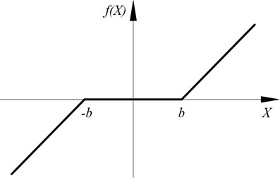
The backlash nonlinearity can be expressed by a piecewise function as illustrated in Fig. 6. is nonlinear function of , and is calculated by Eq. (11) [29]:
where is half of the backlash between the meshing teeth.
Fig. 6Backlash nonlinearity
2.5. Transmission error
Gear transmission error excitation, which is essentially a type of displacement excitation, results from a combination of the gear machining and installation errors, uncoaxiality and gear teeth elastic deformation. Due to gear transmission error, oscillation will occur. The transmission error is set as a sine period function [30]:
where is the transmission error amplitude, is the meshing frequency and is the meshing phase.
2.6. Dimensionless dynamic equation
Rigid displacement, linear and nonlinear resilience are included in Eq. (6). Meanwhile, due to the huge difference among the orders of magnitude of each coefficient, it is difficult to solve the equation by analytical solution. Therefore, dimensionless dynamic equation should be deduced by proper transformation.
Propose where is the average meshing stiffness.
Meanwhile, a displacement scale 1 μm and redefined dimensionless time are introduced, other variables can be deduced as:
The backlash function in Eq. (11) can be transformed as:
The transmission error function in Eq. (12) also can be transformed as:
The dimensionless dynamic equation can be derived by substituting Eqs. (13-15) into Eq. (6):
3. Simulation results and discussion
Due to the strong nonlinear characteristics of the dynamic model involving backlash and transmission error, established in section 3, the fourth-order Runge-Kutta method, ODE45, is adopted for the integration of sets of differential equations. The former 500 periods are discarded, and the last 100 periods are remained for analysis to eliminate the effect of free vibration. Modification coefficient, backlash and transmission error are used as the control parameters to investigate their effects on the system, by means of bifurcation diagrams, Poincaré maps, trajectories and frequency spectrums. System parameters of the KHV are given in Table 2.
Table 2System parameters of the KHV
(kg·m2) | (kg·m2) | (kg·m2) | (kg·m2) | (N·m) | (N·m) | ||
0.03 | 0.15 | 0.2175 | 0.03 | 0.1 | 0.005 | 50 | 50 |
3.1. The effect of modification coefficient
The change of modification coefficient can lead to the change of meshing stiffness which influences dynamic characteristics of the system [27]. Therefore, the study of effect of modification coefficient on the dynamic characteristics is beneficial to improve the dynamic characteristics of the system in design stage.
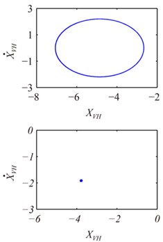
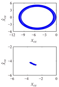
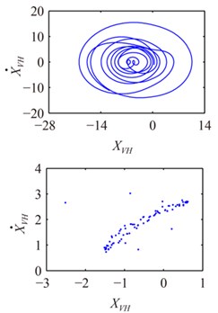
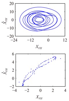
Fig. 7 shows the bifurcation diagram of system using modification coefficient as the control parameter from 0.416 to 0.835 while 2, 5. It can be seen that when is located at the range from 0.416 to 0.565, the motion is synchronous, and only one isolated point is correspondingly shown in Poincaré map for 0.5, as illustrated in Fig. 8a.With the increase in , the response of system comes into quasi-periodic motion ranging from 0.565 to 0.568. Fig. 8b shows the trajectory, Poincaré map and frequency spectrum for 0.565; There are few points limited in certain region in the Poincaré map, closed curves with certain width in the trajectory and continuous bands with 1 peak, 1×, in frequency spectrum. When varies at the interval of [0.568, 0.593], the motion becomes a sub-synchronous vibration with period-five, which can be proved by the five closed curves in the trajectory, five points in the Poincaré map and five peaks, 0.48×, 0.57×, 0.8099×, 1×, 1.2×, in the frequency spectrum for 0.585 as shown in Fig. 8c. When is larger than 0.593, irregular trajectory, discrete points in the Poincaré map as well as the continuous, broad band in frequency spectrum are shown in Fig. 8d for 0.63. All of these results prove that the system motion is chaotic. As increases, the system response leaves chaotic motion and turns into period-six motion. The trajectory, Poincaré map and frequency spectrum for 0.761 illustrated in Fig. 8e convey information in accordance with that in Fig. 7. However, when exceeds 0.768, the points of the attractor in Poincaré map gradually increase, the curves in the trajectory become wined and irregular, continuous and broad band appears in frequency spectrum as shown in Fig. 8f for 0.8, which means that the system comes into chaotic again.
Fig. 7The bifurcation diagram of x1 on the response of system
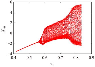
What have been depicted in Figs. 7-8 demonstrate that modification coefficient has great influence on the dynamic behavior of system. When modification coefficient is small, the response of system is period-one motion and the amplitude decreases as modification coefficient increases. Afterwards, the system turns into quasi-periodic motion and alternates between period- ( 5, 6) and chaotic motion, and it can be explained that when the modification coefficient increases, the meshing stiffness becomes small, shock resistance becomes weak, and then the system motion gets more complex.
Fig. 8Poincaré maps, trajectories and frequency spectrums of system at different x1
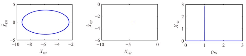
a) 0.5
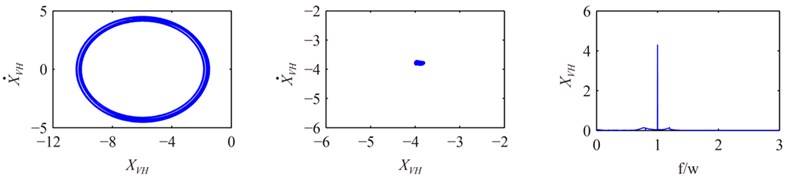
b) 0.565
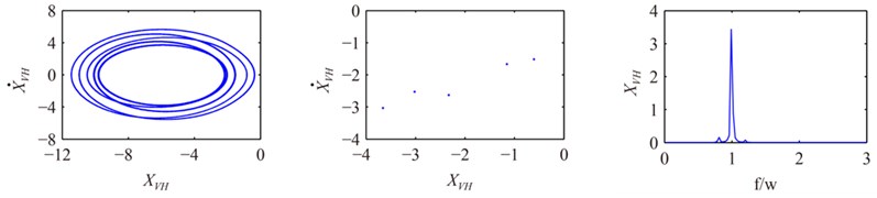
c) 0.585
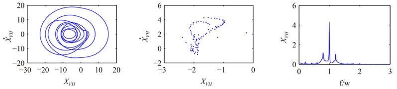
d) 0.63
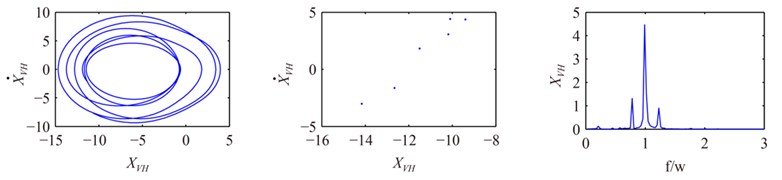
e) 0.761
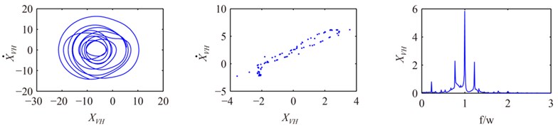
f) 0.8
3.2. The effect of backlash with different modification coefficient
Backlash is inevitable in gear meshing for the purpose of lubrication, machining and assembly errors. The effect of backlash on the dynamic characteristics of the system has been analyzed [31]. However, it is significant to analyze the dynamic characteristics of the system with different modification coefficient, by using the backlash as the control parameter.
The bifurcation diagrams in Fig. 9 show how different influences the effect of backlash on the system at the interval of [0, 2.2] when 5. Regular trajectory, isolate point in the Poincaré map and single peak in frequency spectrum for 0.5 and 0.5 illustrated in Fig. 10a show that the response of the system is period-one motion, which coincides with that in Fig. 9a. However, for the same 0.5, the response becomes quasi-periodic motion for 0.761 as shown in Fig. 9b and Fig. 10b and chaotic motion for 0.83 as shown in Fig. 9c and Fig. 10c, which indicates modification coefficient has significant effects on the response.
Fig. 9The bifurcation diagram of b on the response of system at different x1
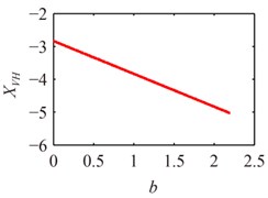
a) 0.5
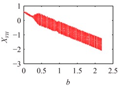
b) 0.761
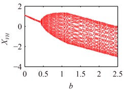
c) 0.83
Fig. 10Poincaré maps and trajectories of system at different x1
a) 0.5
b) 0.761
c) 0.83
According to the above analysis, the response turns into chaotic motion from period-one motion gradually as backlash increases, which is in accord with the results in literature [30], the reasonable explanation is that single contact becomes double contacts with increasing , and the system motion gets more complex. Furthermore, small variation of modification coefficient can result in large change of response, which can be attributed to the combined effect of stiffness and backlash changes caused by the variation of modification coefficient.
3.3. The effect of transmission error with different modification coefficient
The actual line of action will deviate from the theoretical engagement position due to machining error, assembly mistakes and gear teeth deformation, which also leads to variation in instantaneous transmission ratio and undesirable impact between the meshing teeth [31]. Therefore, it is valuable to analyze the dynamic characteristics of the system with different modification coefficient, by using transmission error as the control parameter.
Fig. 11 shows the bifurcation diagram of e on the response of system under different at the interval of [0, 5.5]. It can be seen that the response is synchronous motion with period-one at 4.55 and 0.5 illustrated in Fig. 11a and Fig. 12a. However, the curves in the trajectory become irregular and the points of the attractor in Poincaré map gradually increase for the same as increases, which indicates that the system becomes quasi-periodic motion and chaotic motion from synchronous motion as shown in Figs. 11-12.
Fig. 11The bifurcation diagram of e on the response of system at different x1
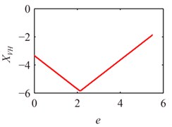
a) 0.5
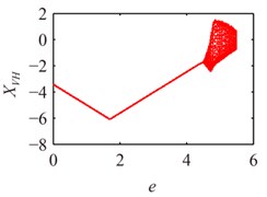
b) 0.63
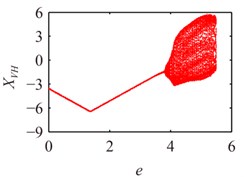
c) 0.83
Fig. 12Poincaré maps and trajectories of system at e= 4.55 at different x1
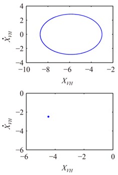
a) 0.5
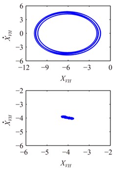
b) 0.63
c) 0.83
The above comparison demonstrates that the response of to the system becomes chaotic motion through synchronous motion and quasi-periodic motion as increases. Meanwhile, the scope of synchronous motion becomes narrower as increases. All results show that modification coefficient makes great effect on the response of to the system.
4. Conclusions
The nonlinear dynamic model is proposed by using Lagrange principle and solved by the fourth-order Runge-Kutta method. Modification coefficient, backlash and transmission error are used as the control parameters to investigate their effects on the system, by means of bifurcation diagrams, Poincaré maps, trajectories and frequency spectrums. The following conclusions can be summarized from the present study:
1) Modification coefficient makes great effect on the dynamic characteristics of PDSTND. When the modification coefficient is small, the response is steady state with period-one and the vibration amplitude decreases as the modification coefficient increases. Afterwards, the system turns into quasi-periodic motion and alternates between period- (5, 6) and chaotic motion, which can be explained as that when the modification coefficient increases, the meshing stiffness becomes small and shock resistance becomes weak, then the system motion gets more complex.
2) Small variation of modification coefficient can result in large change of the response of backlash to system from period motion to chaotic motion, which can be attributed to the combined effect of the stiffness and backlash change caused by the variation of modification coefficient.
3) Modification coefficient influences the response of transmission error to the system. Meanwhile, the scope of synchronous motion becomes narrower with increasing modification coefficient.
References
-
Wu J. Z. The Choice of Modification Coefficient. Journal of Changsha Railway Institute, Vol. 6, Issue 4, 1988, p. 28-34, (in Chinese).
-
ISO/TR 4467. Addendum Modification of the Teeth of Cylindrical Gears for Speed-Reducing and Speed-Increasing Gear Pairs, 1982.
-
PD 6457. Guide to the Application of Addendum Modification to Involute Spur and Helical Gears, 1970.
-
Mirică R. F. On the Distribution of the Profile Shift Coefficients Between Mating Gears in the Case of Cylindrical Gears. 12th IFToMM World Congress, Besancon, France, June 18-21, 2007.
-
International Standard ISO 6336/1. Calculation of Load Capacity of Spur and Helical Gears-Part 1: Basic Principle, Introduction and General Influence Factors, 1993, p. 1-100.
-
International Standard ISO 6336/2. Calculation of Load Capacity of Spur and Helical Gears-Part 2: Calculation of Surface Durability (pitting), 1993, p. 1-28.
-
International Standard ISO 6336/3. Calculation of Load Capacity of Spur and Helical Gears-Part 3: Calculation of Tooth Strength, 1993, p. 1-72.
-
Chen E., Walton D. The optimum design of KHV planetary gears with small tooth differences. International Journal of Machine Tools and Manufacture, Vol. 30, Issue 1, 1990, p. 99-109.
-
Shu X. L. Determination of load sharing factor for planetary gearing with small tooth number difference. Mechanism and Machine Theory, Vol. 30, Issue 2, 1995, p. 313-321.
-
Zhou Y., Shu X. 1st Int. Symp. On Design and Synthesis. Tokyo, Japan, 1984, p. 285-289.
-
Li S. T. Contact problem and numeric method of a planetary drive with small teeth number difference. Mechanism and Machine Theory, Vol. 43, Issue 9, 2008, p. 1065-1086.
-
Xu H. Development of a Generalized Mechanical Efficiency Prediction Methodology for Gear Pairs. Ph. D. Thesis, Ohio State University, 2005.
-
Maldotti S., Bottazzi L., Menegolo L., et al. L'influenza Dello Spostamento dei Profili Sulle Perdite di Potenza Negli Ingranaggi. Proceedings of 36th National Congress of Associazione Italiana per l'Analisi delle Sollecitazioni (AIAS), Naples, Italy, 2007.
-
KISSsoft AG. KISSsoft Calculation Program for Machine Design. Hombrechtikon, Switzerland, 2010.
-
Baglioni S., Cianetti F., Landi L. Influence of the addendum modification on spur gear efficiency. Mechanism and Machine Theory, Vol. 49, Issue 3, 2012, p. 216-233.
-
Ozguven H. N., Houser D. R. Mathematical-models used in gear dynamics: a review. Journal of Sound and Vibration, Vol. 121, Issue 3, 1988, p. 383-411.
-
Velex P., Maatar M. A mathematical-model for analyzing the influence of shape deviations and mounting errors on gear dynamic behavior. Journal of Sound and Vibration, Vol. 191, Issue 5, 1996, p. 629-660.
-
Kahraman A, Blankenship G. W. Experiments on nonlinear dynamic behavior of an oscillator with clearance and periodically time-varying parameters. Journal of Applied Mechanics, Vol. 64, Issue 1, 1997, p. 217-226.
-
Lin J, Parker R. G. Planetary gear parametric instability caused by mesh stiffness variation. Journal Sound and Vibration, Vol. 249, Issue 1, 2002, p. 129-145.
-
Fakher C., Tahar F., Riadh H., et al. Influence of manufacturing errors on the dynamical behavior of planetary gear. International Journal of Advanced Manufacturing Technology, Vol. 27, Issue 7-8, 2006, p. 738-746.
-
Kahraman A. Load sharing characteristics of planetary transmissions. Mechanism and Machine Theory, Vol. 29, Issue 8, 1994, p. 1151-1165.
-
Lin J., Parker R. G. Analytical characterization of the unique properties of planetary gear free vibration. Journal of Vibration and Acoustics, Vol. 121, Issue 3, 1999, p. 316-321.
-
Kahraman A. Free torsional vibration characteristics of compound planetary gear sets. Mechanism and Machine Theory, Vol. 36, Issue 8, 2001, p. 953-971.
-
Baud S., Velex P. Static and dynamic tooth loading in spur and helical geared systems-experiments and model validation. Journal of Mechanical Design, Vol. 124, Issue 2, 2002, p. 334-346.
-
Huang C., Wang J. X., Xiao K., et al. Dynamic characteristics analysis and experimental research on a new type planetary gear apparatus with small tooth number difference. Journal of Mechanical Science and Technology, Vol. 27, Issue 5, 2013, p. 1233-1244.
-
Zhang Z. Practical Gear Design and Calculation. China Machine Press, Beijing, 2011, (in Chinese).
-
Zhang J. Y., Qiu D. M. Method for calculating spur gear mesh stiffness. Journal of Xi’an University of Architecture and Technology, Vol. 28, Issue 2, 1996, p. 134-137, (in Chinese).
-
International Standard ISO 6336/1. Calculation of Load Capacity of Spur and Helical Gears-Part 1: Basic Principle, Introduction and General Influence Factors, 2006, p. 71-75.
-
Kahraman A., Singh R. Non-linear dynamics of a geared rotor-bearing system with multiple clearances. Journal of Sound and Vibration, Vol. 144, Issue 3, 1991, p. 469-506.
-
Zhang C. Mechanical Dynamics. Second Edition, Higher Education Press, Bei Jing, 2008, (in Chinese).
-
Liu Z. H. Research on Dynamic Characteristics of Vehicle Compound Planetary Gear Train Set. Ph. D. Thesis, Wuhan University, 2012, (in Chinese).
About this article
This work was supported by the Key Technologies R&D Program of Tianjin (Grant No. 11ZCKFGX03500).
