Abstract
A single mass nonlinear vibration machine driven by two counter-rotating motors was taken as a research object. Based on the mechanic-electric coupling dynamic equation of the vibration machine and the electromagnetic torque model of motor, the simulation model was established. By using the actual parameters of the vibration machine, the numerical simulation of a single-mass nonlinear vibration system under three typical working states was performed. When two motors were working under the ideal state, or when the overlap angle of two eccentric blocks were different, or when the supply frequency of one motor was changed, the two motors can achieve steadily synchronous motion if parameters of the vibration system are in specific range. Finally, the self-synchronization experiment was carried out under the three working states. A comparison of experimental results with simulation results shows that the numerical simulation is accurate.
1. Introduction
Blekhman I. I. [1-3] developed an algorithmic guide to deriving the conditions for the existence and stability of self-synchronous motions of unbalanced rotors on mechanical systems, which laid the foundation for the research of self-synchronization theory. In the first paper, the electromechanical coupling dynamic equation of a single-mass nonlinear vibration system was established. And the conditions of self-synchronization implementation and stability were deduced. In recent years, many oversea and domestic researchers have already contribution on the simulation field of synchronous system. Xiong Wanli and Zhang Nan [4-5] discussed the transient processes of self-synchronization of vibratory machines under several typical vibration conditions by numerical simulation. Zhao Chunyu [6] performed the simulation of transient process of the vibration system driven by two motors by using VC++ programming. The impacts of the parameters on the self-synchronization condition and the synchronous stable running condition were discussed, which provided a reference for the optimization design of the self-synchronization vibration machine. Hou Yongjun [7] et al. deduced the electromechanical coupling dynamic model of the vibration system driven by three motors and established the simulation model of the vibration system by MATLAB/Simulink. The simulations under sevevral typical conditions were performed and the electromechanical coupling mechanism of the vibration synchronization was analyzed. Balthazar J. M. [8] et al. has also given some comments on self-synchronization of four non-ideal exciters by means of numerical simulation. Czolczynski K. [9] et al. investigated the synchronization of two non-identical self-excited oscillators suspended on the elastic structure by computer simulation. Rumyantsev S. [10] presented also some new results on the numerical simulation of dynamics of vibration transport machines with independently rotating vibration exciters.
In this paper, based on the dynamic model of the vibration machine and the electromagnetic torque model of motor, the simulation model was established. By using the actual parameters of the vibration machine, the self-synchronization simulation under three typical working states was performed. The synchronous motion of the vibrating system and two motors was quantitatively discussed. The simulation results show that the two motors can achieve steadily synchronous motion if parameters of the vibration system are in specific range. Finally, the self-synchronization experiment was carried out under the three working states. A comparison of experimental results with simulation results shows that the numerical simulation is reasonable.
2. The simulation model of the vibrating system
By using SIMULINK which is a simulation tool of MATLAB, a simulation model of the single-mass nonlinear vibration system driven by two counter-rotating motors is established based on the dynamic model of the vibration system and the electromagnetic torque model of two motors. Fig. 1 shows the simulation model of the vibration system.
Fig. 1The simulation model of the vibrating system
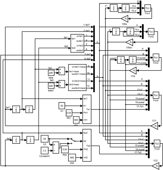
In Fig. 1, the expression in label Fcn1 is:
The expression in label Fcn2 is:
The expression in label Fcn3 is:
The expression in label Fcn4 is:
The expression in label Fcn5 is:
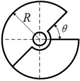
Fig. 2 illustrates the structure chart of one eccentric rotor. The equivalent eccentricity depends on the overlap angle between two eccentric blocks. The relation between equivalent eccentricity and the overlap angle can be expressed as Eq. (1):
where is the actual radius of eccentric rotor; is the areal density of eccentric rotor; is the mass of one eccentric block; is the overlap angle between two eccentric blocks.
Table 1 shows the parameters of the two motors and the vibration machine.
Table 1The parameters of motors and vibration system
The parameters of motors and vibration system | Data |
Moments of inertia of shaft of motor , (kg/m2) | 0.062 |
Overload coefficient of motor | 2 |
Rated power (kW) | 0.04 |
Rated speed of motors (r/min) | 900 |
Grid speed (r/min) | 1000 |
Coefficient of the friction resistance moment of motors (Ns/rad) | 10-6 |
Distance between the rotation center of eccentric rotor and the centroid of vibration mass (m) | 0.1724 |
Actual radius of eccentric rotor (m) | 0.06 |
Included angle between the linkage between the rotation center of eccentric rotor and the mass center of vibration body and horizontal direction (degree) | 30 |
Mass of vibration system (kg) | 38.64 |
Mass of each eccentric rotor (kg) | 3.88 |
Areal density of eccentric rotor (kg/m2) | 171.6 |
Moment of inertia of vibration body (kgm2) | 1.2876 |
Stiffness coefficient in and -axis directions (N/m) | 18761.984 |
Stiffness coefficient of nonlinear spring (N/m) | 2691284 |
Stiffness coefficient in direction (Nm/rad) | 1226.85786 |
Damping coefficient in and -axis directions (Ns/m) | 186.02 |
Damping coefficient in direction (Ns/m) | 16.8 |
Fig. 2The structure chart of eccentric rotor
3. The numerical simulation of the vibrating system under several typical working states
3.1. The numerical simulation under the ideal working state
The ideal working state is the case that the geometrical parameters of the vibrating system are symmetrical, the parameters of two motors are the same and the initial conditions of the system are completely symmetrical. Table 2 shows the simulation data when the vibrating system realizes synchronization. The changing curves of parameters of the vibrating system are obtained in the Fig. 3.
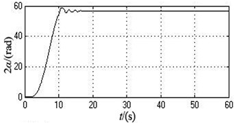
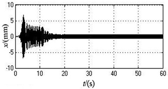
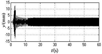
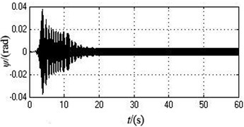
As can be seen from Fig. 3 and Table 2, two motors stay synchronized all the time during the whole starting procedure. The angular velocity curves of two motors remain completely consistent. The value of angular velocity stabilize at around 103.9173 rad/s at 12 s, i.e., 992.3371 r/min. The phase difference of two motors is always 0 and the system realizes phase synchronization. The system only produces displacement in the -axis direction, which reaches about 2.6146 mm after the motors start for 5 s. The displacements of motion in the -axis and directions are both 0.
Fig. 3The simulation curves under the ideal working state
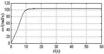
a) The angle velocity
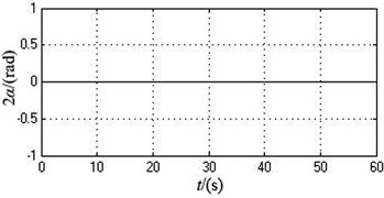
b) The phase difference of motor 1 and 2
c) The displacement in the -axis direction
d) The displacement in the -axis direction
e) The displacement in direction
3.2. The numerical simulation when the overlap angles of two eccentric blocks are different
Table 3 shows the simulation data when the overlap angles between two eccentric blocks of motor 1 and 2 are 60 degree and 90 degree, respectively. Fig. 4 illustrates the simulation curve of the synchronous transition process under this case.
According to Fig. 4 and Table 3, the vibrating system can realize self-synchronization under this case. In the initial stages, the angle velocities of two motors are different. However, they eventually both remain stable at around 103.4341 rad/s after 15 s, i.e., 987.7229 r/min which slightly decreases compared with the value under the ideal working conditions. Therefore, the system can achieve speed synchronization. The phase difference constantly increases and stands at 56.6395 rad after 20 s, which is translated into the value in degree between 0 and 180 degree, i.e., 5.2043 degree which goes up compared with the value under ideal working conditions. The system realizes phase synchronization. Because the mass-radius product of two eccentric rotors are different, the vibrating system has significantly transient oscillations in , and directions at the initial stage. The vibration amplitudes in , and directions all goes up, which are separately 0.5623 mm, 2.9315 mm, and 0.0031 rad.
As can be seen from the simulation result, compared with the values of every parameters under the ideal working conditions, the different overlap angles of two eccentric blocks make the synchronous speed of two motors low, the phase difference large and the amplitude of the vibration body in every directions increase.
Fig. 4The simulation curves when the initial overlap angles of two eccentric blocks are separately 60 degree and 90 degree
a) The angle velocity
b) The phase difference of motor 1 and 2
c) The displacement in the -axis direction
d) The displacement in the -axis direction
e) The displacement in the direction
3.3. The numerical simulation when the supply frequency of one motor changes
During the initial period, the initial supply frequency of the motor 1 and 2 are both 50 Hz. After two motors realize self-synchronization, the supply frequency of the motor 2 is reduced to 46.7 Hz and other parameters are changeless. Table 4 shows the simulation data when the motor 1 and 2 achieve self-synchronization under this case. Fig. 5 illustrates the change curve of every parameters during the operation process.
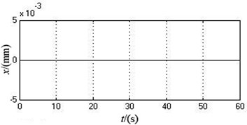
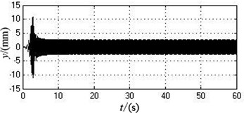
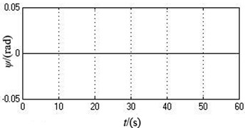
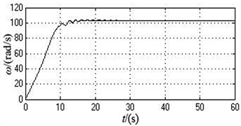
According to Table 4 and Fig. 5, compared with the simulation data under the ideal working state, after the supply frequency of motor 2 is reduced, the synchronous angular velocity decreases from 103.9173 rad/s (992.33871 r/min) to 99.0286 rad/s (945.6535 r/min). The phase difference increases from 0 rad to 0.7183 rad (41.1556 degree). The amplitude in -axis direction goes up from 0 to 0.9434 mm. The amplitude in -axis directions slightly reduced to 2.5025 mm. The amplitude in direction grows from 0 to 0.0051 rad.
As can be seen from the simulation results, compared with the value of each parameter under the ideal working state, when the supply frequency of the motor 2 is reduced to a certain range, the vibration system still can implement self-synchronization. At the moment, the synchronous speed of two motors reduced and the phase difference increased. The amplitude in and directions goes up, but the amplitude in y-axis directions slightly reduced.
Fig. 5The simulation curves when the supply frequency of motor 2 is changed from 50 Hz to 46.7 Hz after 30 seconds
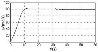
a) The angle velocity
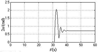
b) The phase difference of motor 1 and 2
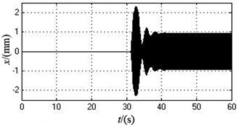
c) The displacement in the -axis direction
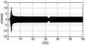
d) The displacement in the -axis direction
e) The displacement in direction
4. The experimental verification and comparison
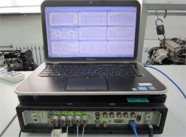
Fig. 6 shows the self-synchronization vibration machine, which consists of two induction motors, one vibration body and four supporting springs. The two motors produce excited force. The size of excited force and the eccentric distance can be adjusted by changing the overlap angle between two eccentric blocks of each motor. The excitation frequency of the vibration machine can be changed by regulating the supply frequency of two motors. The data acquisition and analysis of sensor signal are obtained by B&K vibration testing and analyzing system as shown in Fig. 7.
Fig. 6Self-synchronization vibration machine
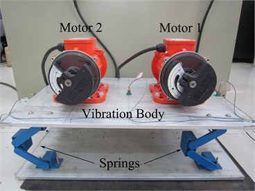
Fig. 7B&K vibration testing and analyzing system
4.1. The experiment under the ideal working state
The supply frequencies of two motors under the ideal working state are both 50 Hz and the overlap angle between two eccentric blocks of every motor are both 60 degree. The structure of vibration system are entirely symmetrical and the initial conditions of two motors are the same. When two motors implement self-synchronization, the experimental data and image of parameters of vibration system are described in Table 2 and Fig. 8.
Fig. 8Experimental curves of parameters under the ideal working state
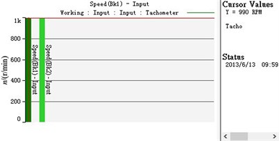
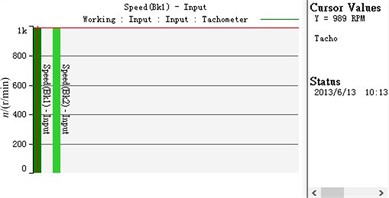
a) The speed of two motors
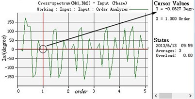
b) The phase difference between two eccentric rotors
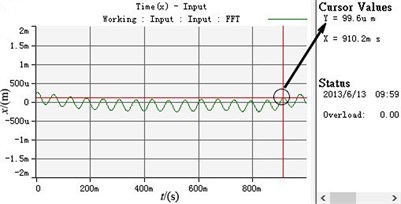
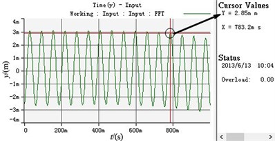
c) The displacement curve in horizontal direction
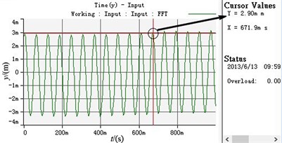
d) The displacement curve in vertical direction
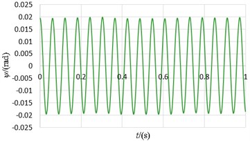
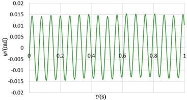
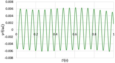
e) The displacement curve in swing direction
As shown in Table 2 and Fig. 8, two motors can realize speed synchronization and the synchronous speed is 990 r/min. The phase difference between two eccentric rotors stands at 0.0627 degree and the system achieves phase synchronization. The vibration body has the stable periodic motion in the horizontal , vertical and swing directions after the motors starts for a period of time. The vibration amplitudes in and directions stabilize at 0.0996 mm and 0.02 rad, which are so low that they can be neglected. The vibration amplitude in -axis directions remain stable at about 2.9 mm.
Table 2Experimental results under the ideal working state
The names of experimental results | The simulation data | The experimental data |
Synchronous angular velocity (r/min) | 992.3371 | 990 |
Synchronous phase difference 2 (degree) | 0 | 0.0627 |
Stabilized amplitude in -axis direction (mm) | 0 | 0.0996 |
Stabilized amplitude in -axis direction (mm) | 2.6146 | 2.9 |
Stabilized amplitude in direction (rad) | 0 | 0.02 |
4.2. The experiment when the overlap angles between two eccentric blocks are different
The supply frequency of two motors are both 50 Hz and the overlap angle between two eccentric blocks of motor 1 and 2 are 60 and 90 degree, respectively. After two motors achieve self-synchronization, the experimental data and images of each parameter of the two motors and the vibration body are shown in Table 3 and Fig. 9.
Fig. 9Experimental curves of parameters when the overlap angles between two eccentric blocks of each motor are different
a) The speed of two motors
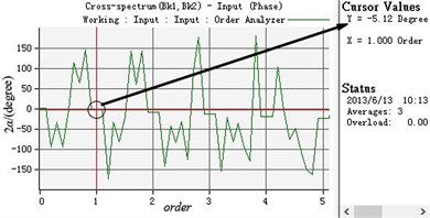
b) The phase difference between two eccentric rotors
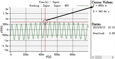
c) The displacement curve in -axis direction
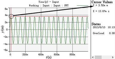
d) The displacement curve in -axis direction
e) The displacement curve in direction
According to Table 3 and Fig. 9, the synchronization speed slightly decreases compared with the data under the ideal working condition and stands at 989 r/min. The phase difference between two eccentric rotors no longer is 0 and stabilizes at 5.12 degree. The vibration amplitudes in the , and directions all increase, which are separately around 0.682 mm, 3.52 mm and 0.014 rad.
Table 3The experimental results under the ideal working state which the overlap angles of two eccentric block are different
The names of experimental results | The simulation data | The experimental data |
Synchronous angular velocity (r/min) | 987.7229 | 989 |
Synchronous phase difference 2 (degree) | 5.2043 | 5.12 |
Stabilized amplitude in -axis direction (mm) | 0.5623 | 0.682 |
Stabilized amplitude in -axis direction (mm) | 2.9315 | 3.52 |
Stabilized amplitude in direction (rad) | 0.0031 | 0.014 |
4.3. The experiment when the supply frequency of one motor is changed
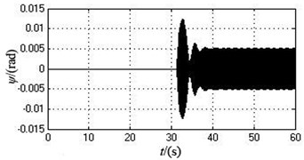
At the initial stage, the supply frequencies of two motors are both 50 Hz. After two motors implement self-synchronization, the supply frequency of motor 2 is adjusted from 50 Hz to 46.5 Hz and other parameters are changeless. The experimental data and images are shown in Table 4 and Fig. 10.
Fig. 10Experimental curve when the supply frequency of motor 2 is changed
a) The speed of two motors
b) The phase difference of two eccentric rotors
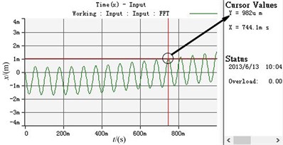
c) The displacement curve in -axis direction
d) The displacement curve in -axis direction
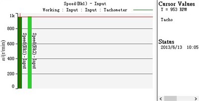
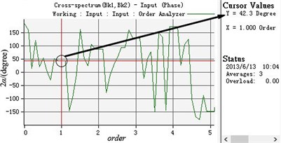
e) The displacement curve in direction
As shown in Table 4 and Fig. 10, two motors still can realize self-synchronization under this case. When the supply frequency of motor 2 decreases, compared with the ideal working state, the synchronous speed decreases from 990 r/min to 953 r/min but the system still can realizes speed synchronization. The phase difference increases to 42.3 degree. The vibration amplitudes in and direction both increase, which are about 0.982 mm and 2.85 mm, respectively. The vibration amplitude in direction declines from 0.02 rad to 0.006 rad.
Table 4The experimental results which the supply frequency of one motor is changed
The names of experimental results | The simulation data | The experimental data |
Synchronous angular velocity (r/min) | 945.6535 | 953 |
Synchronous phase difference 2 (degree) | 41.1556 | 42.3 |
Stabilized amplitude in -axis direction (mm) | 0.9434 | 0.982 |
Stabilized amplitude in -axis direction (mm) | 2.5025 | 2.85 |
Stabilized amplitude in direction (rad) | 0.0051 | 0.006 |
As can be seen from the comparison between the experimental results with simulation results, when the vibration machine is working under the three typical cases, the parameters value are basically similar and the variation trends of each parameter in the three different cases are consistent when the vibration system implements self-synchronization. A good accuracy and effectiveness of the simulation result are verified.
5. Conclusions
Based on the dynamic model of the vibration machine and the electromagnetic torque model of motor obtained in the first paper, the simulation model was established. By using the actual parameters of the vibration machine, the self-synchronization simulation under three typical working states was performed. As can be seen from the simulation results, the vibration system could realize 0-phase self-synchronization under ideal working condition and the vibration body only produces displacement in direction. When the overlap angles between two eccentric blocks of every motors are different, compared with the simulation results under ideal working condition, the synchronization speed of two motors reduces, the phase difference increases and the vibration amplitudes in each direction all go up. When the supply frequency of motor 2 reduced to a certain range, the vibration system still can realize self-synchronization. At this moment, the synchronization speed of two motors reduces, the phase difference increases and the vibration amplitudes in -axis and directions all go up. However, the amplitude in y-axis direction slightly decreases.
The self-synchronization experiment of the vibration machine is conducted. As can be seen from the comparison between the experimental results with simulation results, when the vibration machine is working under the three typical cases, the parameters value are basically similar and the variation trends of each parameter in the three different cases are consistent when the vibration system implements self-synchronization. A good accuracy and effectiveness of the simulation result are verified.
References
-
Belkhman I. I. Synchronization of dynamical System. Nauka, Moscow, 1971, (in Russian).
-
Blekhman I. I. Synchronization in science and technology. New York, ASME Press, 1988, p. 255.
-
Blekhman I. I. Selected topics in vibrational mechanics.World Scientific, Singapore, 2004.
-
Xiong Wanli, He Qing, Wen Bangchun Analysis of transient processes of an electromechanical-coupling self-synchronous system. Journal of Northeastern University, Natural Science, Vol. 21, Issue 4, 2000, p. 158-161, (in Chinese).
-
Zhang Nan, Hou Xiaolin, Wen Bangchun Analysis of synchronous characteristic for self-synchronization system with dual rotors. Transactions of the Chinese Society for Agricultural Machinery, Vol. 40, Issue 4, 2009, p. 184-188, (in Chinese).
-
Zhao Chunyu, Zhu Hongtao, Bai Tianju, et al. Synchronization of two non-identical coupled exciters in a non-resonant vibrating system of linear motion. Part II: Numeric analysis. Shock and Vibration, Vol. 16, 2009, p. 517-528.
-
Hou Yongjun, Yan Guoxing Electromechanical-coupling mechanism of self-synchronous vibrating system with three-motor-driving. Journal of Vibration Engineering, Vol. 19, Issue 3, 2006, p. 354-358, (in Chinese).
-
Balthazar J. M., Palacios Felix J. L., Reyolando M. B. Some comments on the numerical simulation of self-synchronization of four non-ideal exciters. Applied Mathematics and Computation, Vol. 164, 2005, p. 615-625.
-
Czolczynski K., Perlikowski P., Stefariski A., et al. Synchronization of self-excited oscillators suspended on elastic structure. Chaos, Solitons and Fractals, Vol. 32, 2007, p. 937-943.
-
Rumyantsev S., Alexeyeva O., Azarov E., et al. Numerical simulation of non-linear dynamics of vibration transport machines: Recent researchers in engineering and automatic control. Proceedings of the 2nd European Conference of Mechanical Engineering, 2011, p. 10-12.
About this article
This work is supported by National Science Foundation of China (Grant No. 51175071 and No. 51375080) and the Fundamental Research Funds for the Central Universities (Grant No. N120203001).
