Abstract
Technological patterns in the formation of deflections in shape and positioning of apertures in the process of boring are established on the basis of theoretical and experimental analysis. The dominant factors that influence the formation of processing errors were brought to light, taking into account the specificity of the application of PNC machines (programmed numeral control) and specific automatic control systems that position the shape-forming point of a cutting tool by means of the decrement of its oscillations in the process of aperture boring. The need for and possibility of the control of the process of shape formation under boring have been shown, which fundamentally allows to increase the refinement accuracy and to decrease errors in positioning and roughness of the processed surfaces.
1. Introduction
Boring is one of the principal views of the finish cuts of the machining of details of model-frames, slabs, etc., which have big amount of coordinately and diametrically positioned apertures. High demands are made of the apertures of such details, in terms of accuracy of diametrical size, shape and positioning, as well as roughness of the processed surfaces.
The machining of details of the machines on the metal-cutting machine tools usually takes the form of an oscillatory process (i.e. a comparative movement between a detail and a metal-cutting tool), at that amplitude and frequency of these oscillations directly affect the quality of the processed apertures. A characteristic feature of the aperture boring process would be the presence of a unit of technological system, the stiffness of which could not be increased in view of the constructional limitations. Such a unit would be a boring bar with a cutter, an outlet and diameter of which depended on the measurements of a processed surface.
The increase in accuracy of shape and positioning of apertures that are processed by boring with the PNC machines with application of new technologies and machining attachments, guarantees the greatest efficiency of utilization of metal-cutting machines, at the same time combining several technological transitions into one, with the exception of grinding. It is well known that transverse oscillations of a boring bar (in the plane of the radial component cutting force ) mainly form errors in shape and positioning of the processed apertures; the frequency of these oscillations being in the range 200-600 Hz [1].
A significant increase in the accuracy of shape and positioning of the processed apertures could be achieved by means of an active equalizing of the magnitude of transverse oscillations of a boring bar, in the process of cutting, from the modification of the net cutting force. That results in the need for development of and research into new technological methods in order to achieve the required accuracy in the process of high-accuracy aperture boring [2, 3].
Therefore, the development of methods and creation of the controllable machining attachments (CMA) for the increase in accuracy in the process of aperture boring on the PNC machines is very important.
2. The model of the system
For the formation of a control action signal for the controllable machining attachments (CMA), it is necessary to define the magnitude of oscillations of a boring bar according to the degree of rotation of the billet in the process of aperture boring. The billet itself is an input characteristic for the CMA, which also allows for definition of a transfer function of an automatic control system for the ensuring of the input parameters of the cutting process [4].
In the process of aperture boring, the errors in size, positioning and shape depend on the magnitude of oscillations of a boring bar in the process of aperture boring. Thus, for the case in point, the input characteristics for the aperture boring are deflections of the cutting tool point of a boring bar, under the action of variable allowance (which takes the form of an oscillatory process), resulting from geometrical errors of a billet. The output characteristics are the magnitudes of oscillations of a cutting tool from the size of a static setting after the decrement of these oscillations.
We shall describe the process of aperture boring in the form of mathematical relations. The connection of subsystems in one closed elastic system is realised through a zone of cutting, and can be replaced with an operation of component cutting forces , and .
Let’s imagine a dominant oscillatory system (in our case, it is a boring bar) in the form of a solid shaft with a mass m, loaded with the elastic force with a stiffness coefficient , of a generalized shaft along the axes and ; the resisting forces (of decrement) with generalized coefficients , of resistance of the decrement along the respective axes, as well as the component cutting forces and (Fig. 1). Since the impact of the component cutting force leads to the decrease in the magnitude of oscillations in a radial direction, and in the view of the smallness of the first order in comparison to the magnitude of a boring bar from the force , its values can be neglected [5].
With the use of analytic expressions for the active forces in the plane , the mathematical model of the process of boring of a console attached boring bar would be written this way:
where initial conditions for the component cutting forces are:
where , , , are the constants, which depend on the geometry of a tool and characteristics of the processed material. – the modification of thickness of a layer that is being cut; – the width of a layer that is being cut.
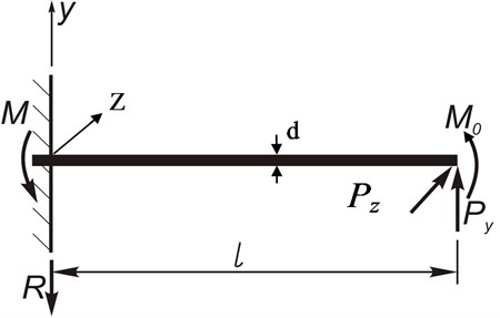
The problem of defining the amplitudes of deflection of the free end point of a rod comes to determination of a value of the flexure of a rod in the examined point. The calculation scheme is presented in the Fig. 2.
The reactions of the supports in the jamming are [6]: , .
The value of the flexure can be determined out of the equation of the lateral flexure of a rod, which look like this:
where is a function of the flexure of the elastic line of a rod, ; – the moment of flection from the radically component cutting force ; – the moment of torsion from the tangential component cutting force ; – the diameter of a rod (Fig. 2); – the stiffness of the plane of the flexure.
Fig. 1A schematic diagram of a dominant oscillatory system in the process of aperture boring under exposure to the component cutting forces PZ and PY
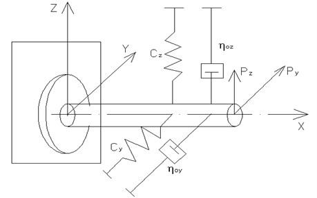
Fig. 2Scheme for definition of the value of the flexure of a boring bar under exposure to the component cutting forces PZ and PY
After differentiating Eq. (1) twice with , we have [6]:
where is a shear; – the intensity of the external load.
The solution of the equations (4) and (5) will be described through an operating method. Let us mark the representation of the function through , i.e. , while the representation of the intensity of the load . After we substitute the representation of derivatives and the representation of the intensity of the load into the equation (4) (Laplas-Karson transform), we get:
The expression derives from the solution of the last equation (6):
Since the intensity of the external load is absent: .
The solution of the differential equation (6) takes up the form of:
Boundary conditions are set as:
Substitute from (2) the values of cutting forces and at taking into account the boundary conditions (9) into the equation (8), and we get:
The equation (10) defines relative offsets of a boring bar under the disturbing forces and , which modify according to the value of the allowance in various angular positions of the billet.
The principal source of the formation of errors in shape and positioning of the processed apertures is the radial component of force , which is acting in transverse direction. Therefore, for the stabilization of the value of the deflection under the effect of a variable of the component cutting force , there needs to be introduced a system of control of the value of the compensating force dependent on the control voltage with feedback loops at the speed and travel of the shape-forming point of a cutting tool.
The transfer function of the inner part of the loop, without taking an integrator into account, will take the form of [7, 8]:
where , .
By analyzing the expression (11) we come to the conclusion that in order to ensure stability, which is inherent in minimum-phase units, the transfer coefficient must have a negative value. With its value being positive, the expression in brackets, which stands in denominator (11), vanishes with an increase in transfer coefficient , which in its turn leads to the system loosing stability. Solving the expression also lead to the border of stability.
Hence, for the stability of a system, it is required to provide a stiff negative feedback at the speed .
A signal amplifier is required for the conversion of a feedback speed signal into a control action signal of the executive component, which ensures the force of the regulation .
A system that is obtained in the process of structural synthesis can be described with an equation of the second order. Using the method of the standard transfer functions, one can define optimal values of the performance (characteristic) equation coefficients (10), which ensure the work of the CMA with given dynamic indicators (oscillation, overcorrection, control time).
3. Experimental analysis of the CMA
The main purpose of a CMA is the automatic control over the boring process. The CMA consists of a controlled system and a control device. Despite the changing outer perturbation actions, the control system must be able to execute predefined functions. While processing apertures by boring, it is necessary to ensure the minimum amplitude of transverse vibrations of a tool, which cause the formation of errors in shape and positioning of the processed apertures [9].
According to the automatic control theory, the electrical part of the developed machining attachments constitutes an automatic control system with feedback (a closed system). Due to the presence of the feedback (COF – coefficient of feedback), there is a possibility of getting information about changes in perturbation actions by means of measuring them. The control over the oscillations of a boring cutting tool is carried out according to the result of those measurements; with an aim of stabilizing its position in relation to the size given in the process of oscillation boring; regardless of the changes in the value of perturbation actions (in our case – the effect of the perturbation forces and ).
In order to predict the expected accuracy of the processing, with given values of the perturbation actions, it is necessary to define a transfer function for the CMA, which allows for defining of the frequency characteristics and characteristics of the transient process of the automatic control system, which in their turn characterize technical opportunities of the CMA in terms of the control over the boring accuracy.
While developing the functional scheme of the CMA, one has to ensure the design parameters of the units of the control system in order to ensure the efficiency of its work. The calculation of the amplitudes of deflections of the shape-forming point of a cutting tool, and the author’s data [10], shows that the elastic displacements in the process of the finishing grinding come to 0.02-0.05 mm.
The parameters of the developed controllable machining attachments (CMA) has to meet the following conditions:
- it is well known that in the overall balance of the oscillations of the technological system, the largest part is induced by the deformation of the boring bar [1, 3, 4, 9]. Therefore, the boring bar has been chosen as an element, the oscillations of which ought to be compensated. Hence, the change in the position of a shape-forming point of a cutting tool in the process of boring, from the effect of cutting forces (which take the form of oscillatory process), can be chosen as an output parameter of the controlled action, according to which the control is executed;
- due to the fact that the first measurement of the deflection of a shape-forming point of a cutting tool is impossible, an indirect method of the deflection measurement has to be used. As a result, displacements of a boring bar from the nominal (given) size, the values of which are controlled by a capacitive transducer located between mobile and immobile parts of the attachment [9], were used as a source of information;
- one has to choose such an actuator for the processing of the control action which will allow for executing the control over the oscillations proportionally to the level of a sensor signal, accurate within the processing of the control action up to 1 micrometer and double-amplitude peak up to 40 micrometers. It would be expedient to apply a piezoelectric electromechanical transformer of movements, or piezoengine [11], as an actuator for the processing of the control action.
While analyzing the effect of a transient process onto the system input, a signal – a single unit step – was being given, and according to the resulted from of the transient process, its characteristics were defined. In the case of the oscillation boring, the transient process is defined by the time of stabilization of the position of a cutting tool point in relation to the rotational axis of a spindle with a billet, while the cutting force is changing.
The technological system can be conditionally divided into two parts – a spindle group, linked to the billet; and a capstan, linked to the tool. In view of the high stiffness of the stand, one can consider the connection between these two groups being carried out through the process of cutting. The stiffness of the spindle group is much higher than the stiffness of the capstan with the tool. Therefore, the elastic displacements (releases) of the tool have a major impact on the accuracy of the processing. The elastic deformations (compliances) of a boring bar have the biggest impact on the accuracy of the processing at the transitions of the boring process.
Fig. 3A schematic diagram of the device for the stabilization of the oscillations of the shape-forming point of the cutting tool in the process of the aperture boring: 1 – a capstan of the machine; 2 – an immobile part of the controllable attachment; 3 – a mobile part of the controllable attachment; 4 – a threaded cone fastening of the attachment; 5 – a piezoelectric transformer of movement (a piezoengine); 6 – a cup for the fastening of the piezoengine; 7 – a sensor of the changes in the deflections of the elastic displacements [releases] of the shape-forming point of a cutting tool; 8 – a sensor that registers the processing of the control action; 9 – preliminary amplifier; 10 – comparator unit; 11 – power amplifier
![A schematic diagram of the device for the stabilization of the oscillations of the shape-forming point of the cutting tool in the process of the aperture boring: 1 – a capstan of the machine; 2 – an immobile part of the controllable attachment; 3 – a mobile part of the controllable attachment; 4 – a threaded cone fastening of the attachment; 5 – a piezoelectric transformer of movement (a piezoengine); 6 – a cup for the fastening of the piezoengine; 7 – a sensor of the changes in the deflections of the elastic displacements [releases] of the shape-forming point of a cutting tool; 8 – a sensor that registers the processing of the control action; 9 – preliminary amplifier; 10 – comparator unit; 11 – power amplifier](https://static-01.extrica.com/articles/14604/14604-img3.jpg)
The suggested CMA for the stabilization of the oscillations of a tool in the process of mechanical processing (Fig. 3) has multiple advantages in comparison to the previously known ones [10, 12]; including a more effective and firm stability of the oscillations of the shape-forming point of a cutting tool in the process of apertures processing. For it is known that the effective control over the oscillations can be ensured by a time constant of the transient process of a system () in 5-10 times smaller period of the oscillations () of the perturbation action. Given such as correlation between and , one can effectively damp general low-frequency components of the oscillations, which characterize errors in shape and positioning of the processed apertures.
Therefore, we introduce the following elements into the device (Fig. 3):
- a sensor of the changes in the deflections of elastic displacements (releases) of the shape-forming point of a cutting tool (position 7 in the Fig. 3), which are in a strict correlation with the change in the value of the cutting force (the perturbation actions);
- a sensor that registers a try-out (adjustment) of the control action (position 8 in the Fig. 3);
- a lift mechanism (position 5 in the Fig. 3) that tries out the control action (the damping of the oscillations of a tool in the process of boring).
As a result, the CMA with principally new qualities is designed. The frame of the device for the automatic control over the oscillations of the tool in the process of aperture boring is fixated in the cutting head (capping) 1 of the metal-cutting machine. It consists of an immobile part of the controllable attachment 2 and a mobile boring bar with a cutter 3, which are linked together through a cone surface 4 with a threaded coupling.
There is a cup made of dielectric material that is placed in the immobile part 2. A piezoelectric transformer 5 is placed inside the cup. The transformer is made of sintered together piezoelectric elements, which in their turn are made of ceramics CТS-19.
The piezoengine possesses the following characteristics: – length (230 mm); – diameter (20 mm); – elongation of the transformer ±45 micrometers under the changing control voltage (±400 В); – frequency of the first mechanical resonance of the piezotransformer which equals (10 kHz) [11].
The immobile frame of the device has an athwart placed projection with a screwed hole, in which the cup is being screwed into 6. The bottom of the cup is an immobile support of the piezoelectric transformer of movements 5 (a piezoengine). When installing the engine into the frame of the device, and in order to eliminate the standoffs in the couplings with the bearing areas, a preload (a preliminary pull) is carried out. The piezoengine is using capacitive transducers of the movements for the measuring of the deflections of the elastic displacements (releases) of the shape-forming point of a cutting tool (sensor 7) and the registration of the processing of the control action (sensor 8). The transduces constitutes in itself a condenser consisting of two plates, one of which is immobile, and the other one is moving.
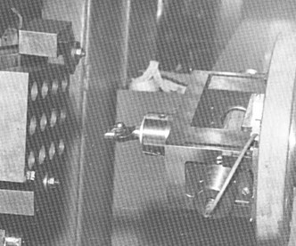
A series of experiments has been carried out for the assessment of the work of the suggested device, as well as for the defining of system’s reaction to the jump in voltage and to the mechanical impact shock-excitation, with the correction of the elastic displacements and without it. The experimental CMA device for the stabilization of the oscillations of a boring bar in the process of aperture processing has been shown in the Fig. 4.
Fig. 4The experimental CMA device for the stabilization of the oscillations of a boring bar in the process of aperture processing
The measurements of size and positioning of the apertures have been executed with a three-coordinated measuring machine LBM “Teylor Hobson Ltd.” A billet is fixated on the table. The position of its processing surfaces is defined in relation to the coordinate axes of the measuring machine.
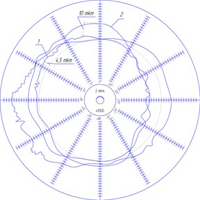
After that, the measurements of the billet are carried out according to the given programme. The definition of the diametrical size and shape of the surface has been executed with a simultaneous recording of the real profile of the surface with a roundness tester RON-Pilot (act of testing No. 131 from 17.08.2012) with a recording of the real profile of the oscillations (Fig. 5).
The positioning of the processed apertures was assessed as a distance from the processing datum surfaces (technological bases) to the centre of the approximating circle of the surface, and between the centres of these circles. The derived regression equations that describe the deflection of the roundness of the cross-sections of the aperture that has been processed without the CMA read:
Fig. 5Circular diagram of the real profile of the cross-sections of the oscillation: 1 – processed with a turned-off CMA; 2 – processed with a turned-on CMA
The coefficients of the regression equations that are executed according to the method suggested in [13] are presented in the Table 1. Moving from the coded values of the factors to the natural ones, we get correlations that describe the deflections of the roundness in a chosen diapason of the cutting regime:
Table 1The values of regression coefficients
Variable of the regression equation | Coefficient of the regression equation | Value of the coefficient of the regression equation | |
With the CMA system | Without the CMA system | ||
15.4838 | 55.3429 | ||
–9.955 | –33.8327 | ||
22.6567 | –78.1748 | ||
–13.7111 | –84.0888 | ||
45.3261 | |||
24.8888 | 70.4173 | ||
159.2888 | |||
297.5601 | |||
The examination of the hypothesis of the adequacy of the models (12), (13), and (14) has shown that their adequacy under the 5 % level of value, for the measuring value of the Fisher information is less than the table one. The comparison of the coefficients has shown that, in average, the deflection of the roundness of the cross-sections of the apertures that have been processed with the CMA is 1.59 times smaller, than when processed without the CMA (Table 1). According to the method of carrying out experimental research, the efficiency of the work of the CMA on the decreasing errors in shape and positioning of the processed apertures, related to the oscillations of the shape-forming point of the cutting tool, has been assessed through the comparison of the coefficients of the decrease in errors in the positioning of apertures, processed with the application of the CMA and without it, as well as through the methods of the mathematical statistics.
The comparison of the coefficients has shown that the errors in the positioning of the apertures processed with the control system are averagely 2.15 times smaller, than when processed without the control system (Table 1).
With the turned on CMA, 83 % of all the details processed during the experiment have reached the tolerance zone of the position deflection, which is limited with the radius of 0.01 mm. When processed without the CMA, it makes only 30 % of the details to reach the tolerance zone, which is three times less. Therefore, the application of the CMA allows for a fundamental increase in the accuracy in positioning of the apertures.
Fig. 6Correlation between the positioning deflecton of aperture and the cutting regimes with the CMA in use (t= 0.6 mm)
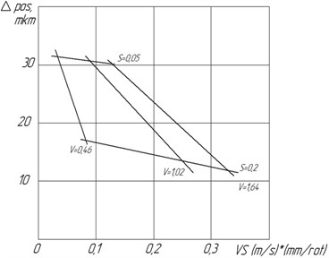
Fig. 7Correlation between the positioning deflecton of aperture and the cutting regimes without the CMA in use (t= 0.6 mm)
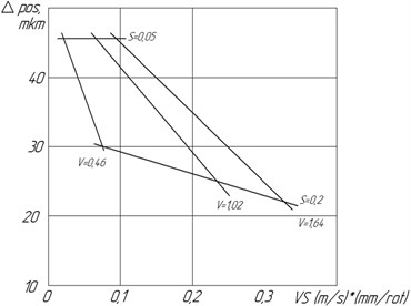
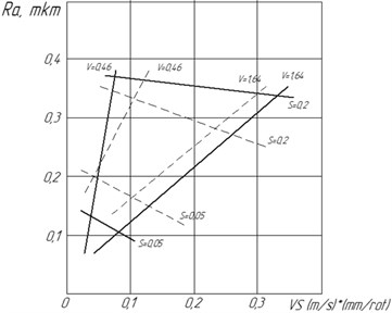
Fig. 8Correlation between the arithmentic average of deflecton of the Ra profile and the cutting regimes (t= 0.6 mm). - - - with the CMA in use; –– without the CMA in use
In the experimental research published in [9], we have defined a quick-action of the CMA, a reaction of the CMA to the jump in voltage without the correction of its dynamic characteristics; a reaction of the CMA with and without the correction to the mechanical impact shock-excitation; a reaction of the CMA with the correction of its dynamic characteristics to the mechanical impact shock-excitation. Continuing with that experimental research, in this work, we have analyzed the impact of the CMA on the parameters of roughness – , , , the errors in positioning of apertures under the cutting regimes, and a positional deflection of the aperture under the cutting regimes (Figs. 6-10).
Fig. 9Correlation between the roughness of Rz profile and the cutting regimes (t= 0.6 mm). - - - with the CMA in use; –– without the CMA in use
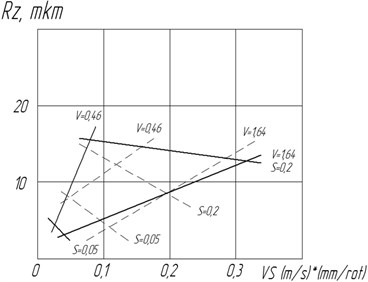
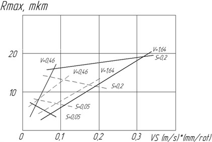
Fig. 10Correlation between the highest peak of roughness Rmaxofile and the cutting regimes (t= 0.6 mm). - - - with the CMA in use; –– without the CMA in use
The correlations of errors in positioning of apertures under the cutting regimes with the turned-on and turned-off CMA are shown in the Figs. 6 and 7, respectively. The decrease in errors in positioning of apertures with the increase in speed of cutting and supply can be traced through the graphics. The smallest error in positioning of apertures is provided with 1.02 m/s, 0.2 mm/rev, 0.6 mm while during the CMA.
4. Conclusions
The analysis of the resulting correlations, presented in the form of graphics in the Figs. 6-10, shows that during the process of boring the CMA impacts on the parameters of roughness and the positioning errors in the processed apertures. Hence, having the depth of cutting 0.6 mm, the increase in speed and decrease in the amount of supply, there is a clear decrease in the arithmentic average of deflecton (Fig. 8) and the height of roughness according to 10 points of (Fig. 9). The highest peak of roughness of the profile insignificantly increases (Fig. 10).
1. On the basis of the carried out research, it has been established that, in the process of the finishing boring (without the use of CMA), the oscillations of the cutting tool point, under the variable forces of cutting ( in the most), have the highest impact on the accuracy in shape and positioning of apertures, which cannot be compensated with traditional methods.
2. The necessity for and the opportunity of the compensation of the oscillations of a boring bar, with its stiffness remaining, have been shown with the help of the controollable machining attachments (CMA).
3. The application of the developed CMA has allowed, in the given diaposone of the cutting regimes, to increase the accuracy in the positioning of apertures in 2.2 times in average, and the accuracy in shape of apertures in the cross-section in 1.59 times in average. When boring with a cutting regime of 1.02 m/c, 0.2 mm/rev, 0.6 mm, a positioning error of 0.1 mm occurs, and an error in shape of the cross-section aperture of not more than 0.008 mm.
4. A fuller realization of the reserves of the increasement in accuracy in shape and positioning of apertures in the cross-section is possible due to the introduction of an emphasis of a trajectory of the cutting tool point, which will decremet the oscillations of a boring bar on the previous transition.
References
-
Muminov N. A. The system of an automatic control over the increase in accuracy in shape of the details in the cross-section under the turning. Self-adjusting Machines, Machinery Construction, 1970, p. 307-311, (in Russian).
-
Sikhimbaev M. R. The control over the accuracy in shape and positioning of apertures, taking the radius of the processing in account. Vestnik KarGTU, Vol. 4, 2010, p. 16-17, (in Russian).
-
Bazrov B. M. The technological basics of the creation of the adaptive control systems of the process of the proccessing of details. Mosstankin, Doctoral Degree Thesis, 1973, p. 47, (in Russian).
-
Sikhimbaev M. R. The control over the elastic displacements of a technological system in the process of boring apertures. Vestnik MKTU Jasaui, Vol. 4, 2010, p. 35-39, (in Russian).
-
Sikhimbaev M. R. The development of the machining attachment for the control over the elastic displacements of a tool in the process of boring apertures. Vestnik, Kazakh-British technical university, Vol. 2, 2011, p. 51-58.
-
Feodosjev V. I. The resistance of materials. Science, 1974, p. 560, (in Russian).
-
Sikhimbaev M. R. The research into the mechanical attachments for the control over the accuracy in shape and positioning of surfaces in the process of boring apertures. Scientific Works of UKGU Auezova University, Vol. 2, 2010, p. 49-54 (in Russian).
-
Sikhimbaev M. R. The application of the machanical attachment in the process of the processing high-accuracy apertures. Fundamental Research – The Publishing House of the Russian Engineering Academy, Vol. 12, 2011, p. 112-116, (in Russian).
-
Sikhimbaev M. R., et al. Experimental studies of stabilization of boring cutter form-building top oscillation. Journal of Vibroengeneering. Vol. 14, Issue 2, 2012, p. 661-670.
-
Kosilova A. G., Meshjerjakov R. K., Kalinin M. A. The accuracy in processing, billet and allowance in machine construction. Technician’s refernce book. Machinery Construction, 1976, p. 356, (in Russian).
-
Bansevicius R. U., Ragulskis K. M. Vibro-engines. Mokslas, Vilnius, 1981, p. 193, (in Russian).
-
VolosovS. S. Product quality management by means of active control. Publishing House of Standards, Moscow, 1989, p. 264.
-
Spiridonov A. A. The planning of experiments when researching technological processes. Machinery Construction, 1981, p. 184, (in Russian).
-
Sikhimbaev M. R. Recommendations for the projecting of a controllable mechining attachments. Materials of the 4-th All-Russian Scientific-Practical Conference: Innovative technologies in machine construction, Kamishin, 2009, p. 136-140, (in Russian).
About this article
