Abstract
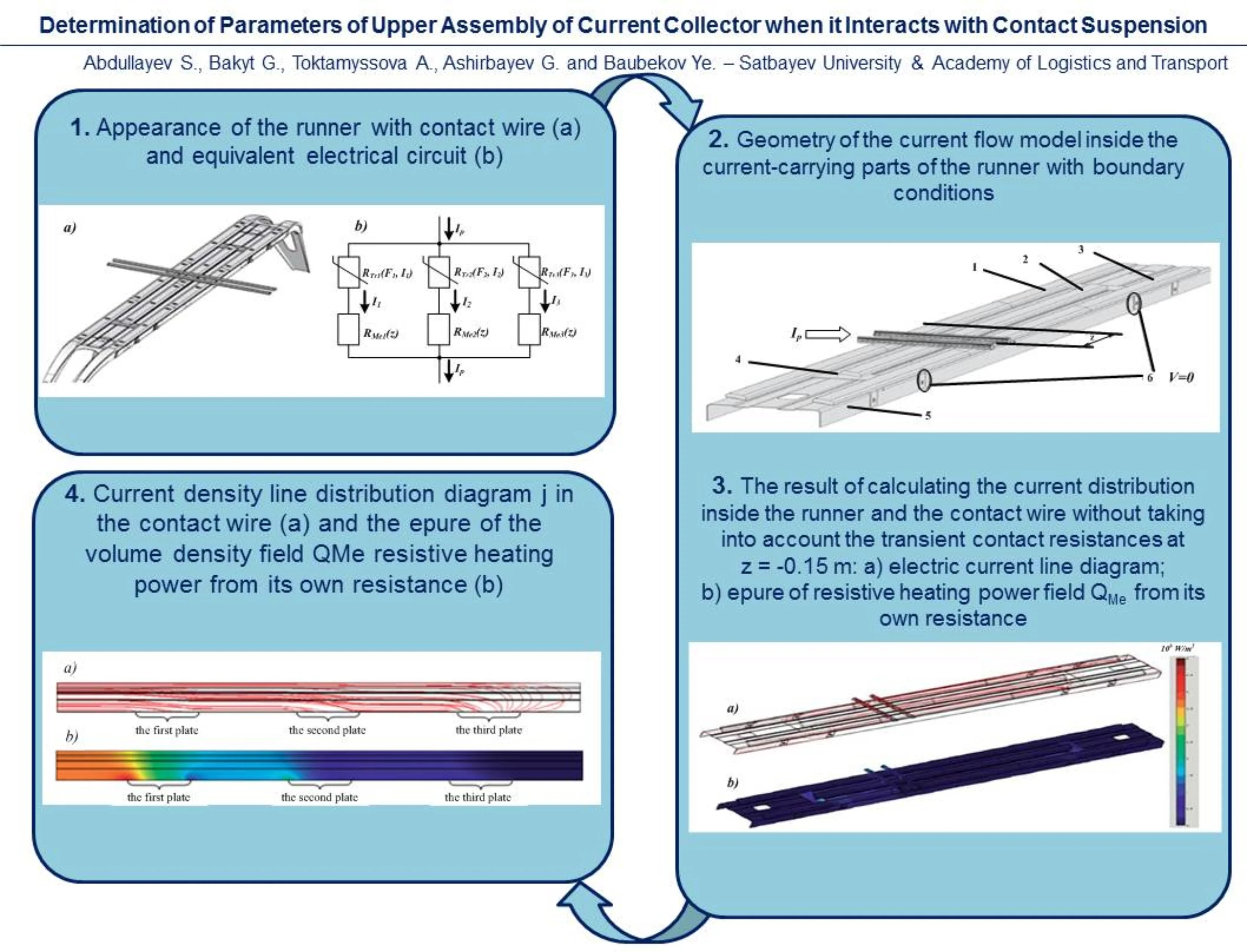
In this article, the definition of the current density field at current collection was reduced only to the calculation of the thermal (resistive) action of the electric current. These procedures must include consideration of the bending stiffness of the contact wires to calculate the distribution of the pressing force on the contact wire between the current collecting plates. Therefore, it is necessary to improve the existing methods for calculating the dynamics of mechanical interaction of the current collector with the chain suspension. As a result of computer modeling in the Comsol Multiphysics software package, the volumetric power density of resistive heating from the intrinsic resistance of the contact wire was determined.
Highlights
- The calculation of contact stresses and deformations during force contact of the contacting elements of the current collection system is performed.
- A model of current flow inside the current-carrying parts of a current collector slide with boundary conditions has been developed.
- Graphs of the dependences on the zigzag parameter of the intrinsic resistance of the slide relative to each plate and the total power of the resistive heating of the slide are obtained.
- As a result of the study, the distribution of current density and volume density of resistive heating from its own resistance inside the contact wire is obtained.
1. Introduction
In the transport system of Kazakhstan, the leading and organizing mode of transport is railway transport. In the foreseeable future, rail transportation will not be an alternative in terms of economic efficiency and environmental safety during transportation of significant stable flows of mass cargo delivered over medium and long distances, as well as to ensure passenger transportation [1].
It is known that the life of the trolley wire depends on a variety of influencing factors, most of which determine mainly the average wear of the wire. Only the nature of contact pressure changes significantly affects the uneven wear of the contact wire: with a large difference in contact pressure, separate zones with increased wear appear on the contact wire.
The relevance of the theme is due to the fact that an increase in the speed of electric rolling stock (ERS) up to 250 km/h, as shown by domestic and foreign experience, significantly worsens the dynamic conditions for interaction of the current collector with the contact suspension and, in addition, reduces the safety of ERS operation [2].
2. Methods
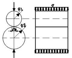
Caption of Stresses and deformations arising from the force contact of two bodies are called contact bodies. When two cylinders of radii and , in contact are compressed, with parallel axes loaded with uniformly distributed load of intensity (Fig. 1), the contact area has the form of a narrow strip with width 2. Half width of the contact strip [3]:
Here the minus sign is taken if the cylinder of radius rests on concave cylindrical surface of radius. Maximum pressure at points of contact site axis:
By contacting the cylinder of radius and the plane, the highest pressure can be obtained by taking :
Evaluation of contact stress strength for plastic materials is made using the third or fourth strength theory. Equivalent stresses according to the third strength theory:
on the fourth:
Fig. 1Diagram of application of forces at contact of cylinders of different radius
For strength calculation it is necessary to determine the largest values equivalent stresses. The most dangerous point is at some depth under the center of the site. Thus, for the strip contact area, the maximum equivalent stress will be at , stress , at 0.76.
Maximum values of equivalent voltages depend mainly on from the highest pressure . Therefore, often strength calculation in places contact is performed by the highest pressure along the contact site, comparing it with the corresponding allowable value []. In this case, strength condition [4]:
where – ratio of the highest equivalent stresses according to the corresponding theory of strength to pressure .
The value of m depends on the ratio of the lengths of the semi-axes and of the elliptic contour of the contact site. For example, at ratios / equal to 1; 0.75; 0.5; 0.25 and 0, values for the third strength theory, respectively are 0.620; 0.625; 0.649; 0.646 and 0.6.
3. Results
In the process of current collection inside the runner and on the section of the contact wire directly connected to the runner, a constant change in the distribution of the current density occurs.
In general, the transient resistance (current-collecting plate – contact wire) depends on their grades, the state of the surfaces, the force of pressing the runner plate on the wire , the value of the current preleasing through this transient resistance, and its temperature [5]. In this case, it is assumed that the transient resistance is a nonlinear element dependent only on and . The influence of temperature, the quality of treatment of the working surfaces of the wire and plates is not taken into account. The relationship for HPLT plates was approximated according to the results of experiments given in the literature [6]. The approximation is given by the following algebraic expression proposed by one of the authors:
where – limit value of transient resistance at current trending to infinity, Ohm; – coefficient of increasing the ultimate transient resistance at low current values.
Diagrams of functions and are shown in Fig. 2.
Fig. 2Function graphs: a) RrF and b) ψI
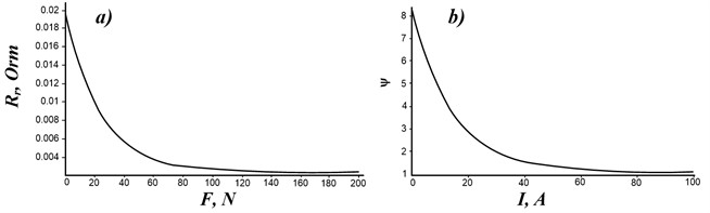
It is generally accepted that the value of transient resistance is proportional to the pressing force of contacts [7]. Therefore, the graph is a hyperbola, and at 0 the transient resistance . In this case, it is considered that when 0 is pressed, an arc having a finite ohm resistance occurs.
The own resistance of the runner relative to each plate is dependent on the location of the wires on the runner. Due to the zigzag, the contact wire is constantly moving along the skid. If we assume that the electric locomotive is moving in a straight section of the path, then the center of the runner will be above the axis of the path. In this case, for the parameter characterizing the position of the contact wire on the runner, it is convenient to take the distance from the center of the runner to the wire (it is assumed that the contact wire is parallel to the track axis). The plot along the path is a saw tooth curve. The maxima and minima coincide in the abscissa coordinate with the coordinates of the supports, and the parameter itself is equal to either a positive zigzag of 0.3 m or a negative zigzag of 0.3 m [4].
The Comsol Multiphysics 3.5 a software package based on the finite element principle is used to simulate electrical processes directly throughout the contact wire and runner [2]. To describe the current flow inside the current-carrying parts of the runner and wire, the continuity equation (Ohm’s law in differential form) for stationary currents is used [8]:
where – potential, V; – specific conductivity Cm/m; – gradient operator.
After solving Eq. (7), the electric field strength vector, V/m, is determined:
Next, an electric current density vector is calculated; A/mg:
Volumetric density of resistive heating depends on current density and is determined by the formula W/m3:
where – specific electrical resistance of the material, Ohm-m.
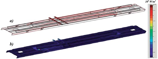
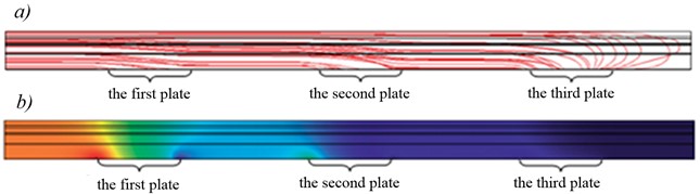
As a result of solving Eqs. (8-11) with given parameters and boundary conditions, values of potential field , electric field intensity , current density field , resistive heating power field from intrinsic resistance over the whole volume of the runner and contact wire are determined. For the parameter –0.15 m and current 1600 A, the calculation result is shown in Fig. 3.
Fig. 3The result of calculating the current distribution inside the runner and the contact wire without taking into account the transient contact resistances at z= –0.15 m: a) electric current line diagram; b) epure of resistive heating power field QMe from its own resistance
4. Discussion
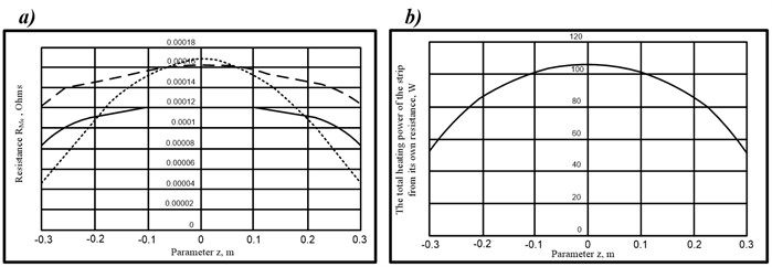
After calculating the current distribution inside the runner and the wire, the value of the current flowing from the contact wire to each of the plates HSSW, is determined. Further, based on the equivalent scheme, the values of the natural resistances of the runner relative to each with plate are determined taking into account the assumption that the transient resistances are zero, i.e. 0. At the same value of the total current of the runner and the absence of transient resistances, the calculation result will depend only on the parameter (Fig. 4) [9].
From the Fig. 4 shows that the greatest values of the own resistance of the runner relative to each of the plates and the greatest total resistive heating of the runner from these resistances when the contact wire is located in the middle of the runner 0. The smallest values and when the contact wire is shifted from the center of the runner by the zigzag ±0,3 m. This result is easy to explain. Since the points of connection of current-conducting conductors to runner 6 (Fig. 7) are spaced apart from the center of the runner, at 0 the path of current flow through the runner is the greatest [10].
Accordingly, the resistances and heating also greatest. At ±0.3 m, the situation is opposite. From the analysis of the field diagrams of the volumetric density of the power of resistive heating of the runner from its own resistance , it is visible that the heating power is distributed over the runner extremely unevenly. Description of this model is given in [5]. This model does not take into account the distribution of pressure across the plates. In order to do this, it is necessary to take into account the bending rigidity of the contact wire. Therefore, the results of the calculation of the pressing force of the entire running of the current collector from the above model were converted to pressing each individual plate on the contact wire, taking into account its bending rigidity.
Fig. 4Graphs of dependencies on the parameter z: a) of the own resistance RMe of the runner relative to each plate HSSW, b) of the total power of resistive heating of the runner PMeΣ on the own resistance
Heating power in transient resistance - current collecting plate – contact wire is according to Joule-Lenz law:
Therefore, in the immediate vicinity of the runner, the resistive heating field caused by the intrinsic resistance of the contact wire is unevenly distributed within it. This field is non-static and depends on the magnitude of the currents taken by each plate it. Fig. 5 shows the distribution of current density and volumetric density of resistive heating from intrinsic resistance inside the contact wire. The result shown in Fig. 8 is obtained from the condition that the current taken by each HPLT plate in this case is equal to the average value of the current in time , which is taken by this plate when the pressure changes in time. In other words, the field in Fig. 8 is obtained averaged by the value of currents . Similar to the case with a slide, the time-varying field is replaced by this stationary averaged field .
Fig. 5a) Current density line distribution diagram j in the contact wire and b) the epure of the volume density field QMe resistive heating power from its own resistance
5. Conclusions
After analyzing the effect of pressing forces on the contact wire on the plates, it can be concluded that the more evenly distributed the pressing, the more evenly distributed the current load between the plates.
If the pressing is distributed unevenly between the plates, then the plate with a large pressing accounts for most of the current of the ERS, and the plate with a smaller pressing – correspondingly less.
The results obtained during computer modeling based on the Comsol Multiphysics software package showed that the first plate of the pantograph is strongly heated by the contact wire.
The results of this study make it possible to determine in a timely manner the causes of failure of the plates of current collectors of electric rolling stock and show the need to continue in-depth experimental research in this direction, which will be reflected in other research papers.
References
-
A. Wilk et al., “Novel method of estimation of inertial and dissipative parameters of a railway pantograph model,” Vehicle System Dynamics, Vol. 60, No. 7, pp. 2413–2435, Jul. 2022, https://doi.org/10.1080/00423114.2021.1901942
-
S. Abdullayev, J. Musayev, T. Chigambaev, S. Malybayev, G. Bakyt, and A. Toilybayev, “Optimum distribution of repairs in RS-8 of electric locomotives Vl80сbetween repair depots in the Republic of Kazakhstan,” Transport Problems, Vol. 12, No. 2, pp. 19–29, Oct. 2017, https://doi.org/10.20858/tp.2017.12.2.3
-
M. Yamada, T. Watanabe, T. Gunji, J. Wu, and F. Matsumoto, “Review of the design of current collectors for improving the battery performance in lithium-ion and post-lithium-ion batteries,” Electrochem, Vol. 1, No. 2, pp. 124–159, May 2020, https://doi.org/10.3390/electrochem1020011
-
S. Abdullayev, G. Imasheva, N. Tomkurzina, N. Adilova, and G. Bakyt, “Prospects for the use of gondola cars on bogies of model ZK1 in the organization of heavy freight traffic in the Republic of Kazakhstan,” Mechanics, Vol. 24, No. 1, pp. 32–36, Feb. 2018, https://doi.org/10.5755/j01.mech.24.1.17710
-
M. Kuźnar, “Damage caused by material defects of carbon composites used on various types of railway pantographs,” Materials, Vol. 16, No. 5, p. 1839, Feb. 2023, https://doi.org/10.3390/ma16051839
-
A. Abdullayeva, A. Kalabayeva, A. Ivanov, S. Abdullayev, and G. Bakyt, “Methods for identification of complex industrial control objects on their accelerating characteristics,” Communications – Scientific letters of the University of Zilina, Vol. 24, No. 3, pp. B239–B246, Jul. 2022, https://doi.org/10.26552/com.c.2022.3.b239-b246
-
C. Yi, D. Wang, L. Zhou, and J. Lin, “A simulation investigation on the influence of pantograph crack defect on graphite contact strip wear,” Engineering Failure Analysis, Vol. 131, p. 105889, Jan. 2022, https://doi.org/10.1016/j.engfailanal.2021.105889
-
G. Mei, W. Fu, G. Chen, and W. Zhang, “Effect of high-density current on the wear of carbon sliders against Cu-Ag wires,” Wear, Vol. 452-453, p. 203275, Jul. 2020, https://doi.org/10.1016/j.wear.2020.203275
-
M. O. Mussabekov, G. B. Bakyt, A. M. Omirbek, E. Brumerčíková, and B. Buková, “Shunting Locomotives Fuel and Power Resources Decrease,” MATEC Web of Conferences, Vol. 134, p. 00041, Nov. 2017, https://doi.org/10.1051/matecconf/201713400041
-
A. P. Barnes, C. Svensson, and T. R. Kjeldsen, “North Atlantic air pressure and temperature conditions associated with heavy rainfall in Great Britain,” International Journal of Climatology, Vol. 42, No. 5, pp. 3190–3207, Nov. 2021, https://doi.org/10.1002/joc.7414
About this article

The authors express their gratitude to the leadership of the Academy of Logistics and Transport for this opportunity to participate in the conference.
The datasets generated during and/or analyzed during the current study are available from the corresponding author on reasonable request.
The authors declare that they have no conflict of interest.
